6.3.2.2 Contributions to the Gate
Capacitance
To investigate the dependence of CG on dGC
and LG the different contributions to CG
are separated by simulation according to (62).

In Section 6.2 a possible reduction of A2
by optimization of the Tgate shape was discussed. A change of dGC
is expected to have only an impact on the parameters A1
and A2 which are attributed to the epitaxial structure.
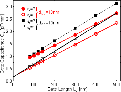
In Figure
6.45 the simulated CG versus LG
is shown for dGC = 10 nm and for dGC
= 13 nm both for the passivated and unpassivated case. As demonstrated
in Section 6.1.2.2 and 6.2.3.2
the parameters A1, 10, A2, 10, and
A3, 10 for the device with dGC = 10
nm and A1, 13, A2, 13, and A3,
13 for the device with dGC = 13 nm can be deduced.
The parameters for both dGC are given in Table
6.5. To investigate the dependence of CG on dGC
and LG the different contributions to CG
are separated by simulation according to (62).
|
|
|
|
|
|
|
|
|
|
|
|
|
|
|
The fringe capacitances purely attributed to the epitaxial layers A1,
10 is slightly lower than A1, 13. As expected
the values of A2 which are related to the coupling of
the contacts are very similar. But for A3 substantial
differences occur. Due to the smaller dGC A3,
10 is greatly increased to 5.1 nF/mm2 compared to
A3, 13 = 4.3 nF/mm2. Thus to improve fT
by a reduction of dGC a large part of the improvements
of gm is compensated by the significant increase in CG.
Helmut Brech 1998-03-11