
 .
.After the critical thickness, threading dislocations glide along the interface of a lattice mismatched bilayer with the concomitant formation of misfit segments. The misfit segment is called misfit dislocation because its formation is caused by the relaxation of the misfit strain associated with the lattice mismatch. At the critical thickness, the formation of misfit dislocations is energetically favorable as they relax the internal energy. Increasing the film thickness after the critical value, the evolution of the misfit dislocation density was modeled by Hu [31]. The model is based on balancing the elastic energy from a partially relaxed misfit strain and the energy of the non-interacting misfit dislocation arrays. The main hypothesis is that all misfit dislocations appear suddenly when the film thickness reaches the critical value. There is no reason to assume that this happens but this assumption is retained to keep the equations simple, thus avoiding the inclusion of any kinetic parameter into the treatment. Hu’s expression [31] for the misfit dislocation density ρMD after the critical thickness reads as follows:
| ρMD = . | (5.4) |
| |ϵ| = ||ϵm|- ρb sin θ sin ϕ|, | (5.5) |
A similar formula of misfit dislocation density was derived by Holec [24] for the hexagonal symmetry:
ρMD =   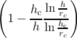 . . | (5.6) |
|ϵ| = ||ϵm|-| ρb sin θ sin ϕ||. ρb sin θ sin ϕ||. | (5.7) |
Figure 5.7 shows that the dislocation density approaches the limit for an infinitely thick layer quite rapidly, indicated by the dashed lines. The figure also shows the difference between the two models. The misfit dislocation density increases faster when Hu’s model [31] is used. The difference between the final values of the density after the saturation point is around 25%.
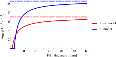
Regarding the stress relaxation, Hu’s model [31] predicts a slightly lower residual strain compared to Holec’s model [24], but the difference between the two is negligible. The two models have the same asymptotical value corresponding to the same in-plane strain, i.e., the complete relaxation.
| Figure 5.7: | The misfit dislocation density ρMD, calculated within the isotropic and anisotropic frameworks, as function of the film thickness h. |
| Figure 5.8: | The in-plane strain ε, calculated within the isotropic and anisotropic frameworks, as function of the film thickness h. |
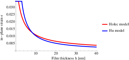
Holec model [24] is used to calculate the misfit dislocation density and the strain relaxation in Al1-xGaxN film grown upon an AlN substrate for x=25%, 50%, 75%, and 100%. The critical thickness is evaluated according to Steeds [72]. Figure 5.9 shows that in increasing the lattice mismatch between film and substrate, the misfit dislocation density increases as well as the corresponding asymptotical value. In particular, in increasing the lattice mismatch, the increase of the misfit dislocation density is faster in the early stage of the growth and then slows down.
Figure 5.9 shows also that the saturation of the misfit dislocation density is almost reached at 50nm. Temperature can delay the development of the misfit dislocation density. Kinetic parameters are not considered in this work but the delay of the misfit dislocation elongation is negligible at typical processing temperatures of III-nitrides, which is around 1000∘C [11].
| Figure 5.9: | The misfit dislocation density ρMD, calculated within the anisotropic framework, as a function of the film thickness h for different chemical compositions of the film alloy. |
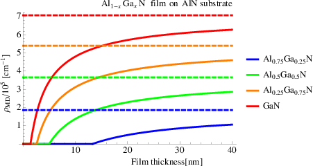
A relaxation of the misfit stress results from the elongation of the misfit dislocations. The stress relaxation has been evaluated for an Al1-xGaxN film grown upon an AlN substrate for x=25%, 50%, 75%, and 100%. The results are shown in Figure 5.10, where the strain decrease is a function of the film thickness. In particular, the decrease is faster for a high lattice mismatched film than for low ones. Another observation of Figure 5.10 is that the curves overlap after a certain point and they have the same asymptotical value which corresponds to the complete relaxation of the structure. It is important to observe that the in-plane strain is still not relaxed after 40nm. In particular, it is still 1/2 and 1/6 of the initial misfit strain for Al0.75Ga0.25N and GaN films respectively.
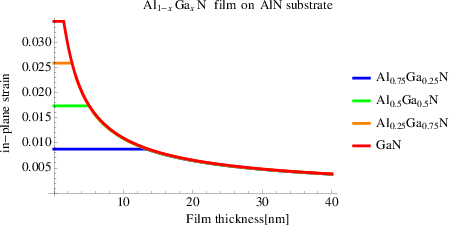
| Figure 5.10: | The in-plane strain as a function of the film thickness h for different initial conditions. |