2.3 Transformations
The material constants cij or sij for a particular material are usually specified in a basis
with coordinate axes aligned with particular symmetry planes (if any) in the material.
When solving problems involving anisotropic materials it is frequently necessary to
transform these values to a coordinate system that is oriented in some convenient way
relative to the boundaries of the solid. The basis transformation formulas are listed below
and are used for the calculation of the dislocation energy in Chapter 3. To this end, let’s
suppose that the components of the stiffness tensor are given in a basis, {e1,e2,e3},
and we wish to determine its components in a second basis, {m1,m2,m3}. We
define the transformation tensor Ω with components Ωij = mj ⋅ ej, or in matrix
form
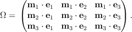 | (2.30) |
This is a symmetric tensor satisfying ΩΩT = ΩTΩ = I. In practice, the transformation
tensor can be computed in terms of the angles between the basis vectors. It is
straightforward to show that stress, strain and elasticity tensors transform as
| σij(m) = Ω
ikσkl(e)Ω
jl, | |
|
| sij(m) = Ω
ikσkl(e)σ
jl, | |
|
| cijkl(m) = Ω
ipΩjqcpqrs(e)Ω
krΩls. | (2.31) |
The basis transformation formula for the stiffness tensor C is more conveniently expressed in
matrix form as
where the rotation matrix K is computed as
K =  , , | | (2.33) |
and
| Kij1 = | Ω
ij2, | |
|
| Kij2 = | Ω
imod(j+1,3)Ωimod(j+2,3), | |
|
| Kij3 = | Ω
mod(i+1,3)jΩmod(i+2,3)j, | |
|
| Kij4 = | Ω
mod(i+1,3)mod(j+1,3)Ωmod(j+2,3)mod(j+2,3)+ | |
|
| Ωmod(i+1,3)mod(j+2,3)Ωmod(i+2,3)mod(j+1,3), | |
|
| with | i,j = 1, 2, 3. | (2.34) |
The modulo function satisfies
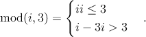 | (2.35) |
The basis change for the compliance tensor (the inverse of the stiffness tensor) follows
as
| S(m) = K-TS(e)K-1, | | (2.36) |
where
K-T =  . . | | (2.37) |
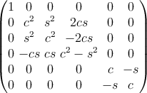
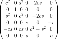
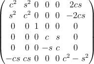
The proof of these expressions is given in Ting [74]. For the particular case of rotation
around an angle θ in a counterclockwise sense about the x,y,z axes, the rotation matrix
reduces, respectively, to
where c = cos θ and s = sin θ. The inverse matrix K-1 can be obtained simply by changing
the sign of the angle θ in each rotation matrix. Clearly, applying the three rotations
successively can produce an arbitrary orientation change.
 ,
,