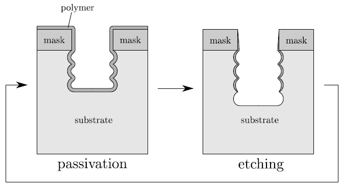
The multi-LS technique, in combination with directional etching, enables the simulation of a Bosch process using a simplified model. The Bosch process is used for high aspect ratio etching by alternating passivation and etching cycles [67]. The deposition of a passivation layer protects the side walls from chemical etching during the subsequent etching cycle. Directional etching caused by ion bombardment removes the passivation layer at the bottom, so that the radicals are able to attack the substrate. The basic principle of a Bosch process is shown in Figure 4.15.
|
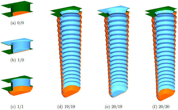
In a simplified model chemical etching and deposition can be assumed to be isotropic. Physical etching due to ions is regarded as perfect directional. Figure 4.16 shows the development of a
![]() -hole during a Bosch process. The deposition rate has been set to
-hole during a Bosch process. The deposition rate has been set to
![]() . The chemical etch rate has been
. The chemical etch rate has been
![]() ,
,
![]() , and
, and
![]() for the passivation layer, the mask, and the substrate, respectively.
for the passivation layer, the mask, and the substrate, respectively.
![]() ,
,
![]() , and
, and
![]() have been the corresponding directional etch rates. 20 cycles with
have been the corresponding directional etch rates. 20 cycles with
![]() deposition and
deposition and
![]() etching were computed. The grid spacing has been set to
etching were computed. The grid spacing has been set to
![]() which corresponds to lateral grid extensions of
which corresponds to lateral grid extensions of
![]() . For the time evolution
. For the time evolution
![]() has been used.
has been used.
 |
The Bosch process is also an example which requires an accurate description of the thin passivation layer. Furthermore, the accurate resolution of the material-dependent surface velocities over time reduces the accumulation of large errors. Since all applied methods including the time evolution and the visibility check can be performed in linear time, the calculation of this simplified Bosch process is very fast. The computation time on an Intel Core 2 Duo E6600 processor clocking at
![]() is approximately
is approximately
![]() .
.