If a non-static data structure, such as the H-RLE data structure, is used instead of a full grid, parallelization is more complicated. As described previously in Section 4.3 the data structure must be rebuilt several times for every time step. Adding grid points to the data structure is only possible sequentially and in lexicographical order, and hence cannot be accomplished in parallel. A solution of this problem is to use as many H-RLE data structures as CPUs. This way, each thread may add grid points to its own H-RLE data structure at the same time. However, it must be ensured that all grid points are processed by exactly one thread. Therefore, the entire grid needs to be partitioned in advance. In order to maintain all the good properties of the H-RLE data structure, such as the fast sequential access and the small memory requirements, it is advantageous to divide the grid into sequences of grid points which contain approximately an equal number of active or defined grid points.
If
![]() CPUs are used, the partitioning is characterized by
CPUs are used, the partitioning is characterized by
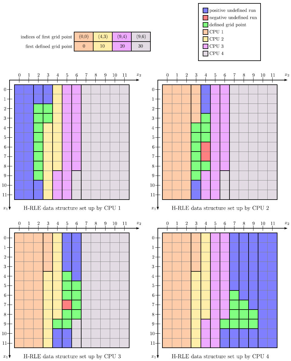
![]() index vectors. Each index vector represents the start of a sequence of consecutive grid points, which is assigned to a thread and which is stored in the corresponding H-RLE data structure. For grid points stored in the H-RLE data structure of another thread, new run codes are introduced. For each CPU a new run code is defined, which provides information which H-RLE data structure houses the corresponding grid points. Figure 4.20 demonstrates the parallelization of the example given in Figure 3.6 and Figure 3.7. There, the LS values and undefined runs are distributed over four separate H-RLE data structures.
index vectors. Each index vector represents the start of a sequence of consecutive grid points, which is assigned to a thread and which is stored in the corresponding H-RLE data structure. For grid points stored in the H-RLE data structure of another thread, new run codes are introduced. For each CPU a new run code is defined, which provides information which H-RLE data structure houses the corresponding grid points. Figure 4.20 demonstrates the parallelization of the example given in Figure 3.6 and Figure 3.7. There, the LS values and undefined runs are distributed over four separate H-RLE data structures.
|