Next: 3.2.2 Separating Material Interfaces Up: 3.2 Oxidation Modeling using Previous: 3.2 Oxidation Modeling using
In order to model multiple moving interfaces in the LS method from Section 1.4.1, two separate LS systems are
analyzed. One system is used for the Si-SiO![]() interface, which is an etch-like process, proceeding with a relative
negative velocity, while a separate system is used for the SiO
interface, which is an etch-like process, proceeding with a relative
negative velocity, while a separate system is used for the SiO![]() -ambient interface, which is a deposition-like process,
proceeding with a relative positive velocity. Three different scenarios can lead to different methods by which the
LS system should be described: An initial LS description of one interface, which will grow to two interfaces at the onset
of oxidation, pre-grown material such as a native oxide layer which will grow further during the oxidation process, and
the existence of a mask layer, which should affect the movement of both interfaces.
-ambient interface, which is a deposition-like process,
proceeding with a relative positive velocity. Three different scenarios can lead to different methods by which the
LS system should be described: An initial LS description of one interface, which will grow to two interfaces at the onset
of oxidation, pre-grown material such as a native oxide layer which will grow further during the oxidation process, and
the existence of a mask layer, which should affect the movement of both interfaces.
When the initial geometry is described by a single material interface, which must split and simultaneously move in opposite directions,
the LS systems are straightforwardly implemented. If we label the initial interface ![]() , then the split is performed
by simply introducing a new LS interface
, then the split is performed
by simply introducing a new LS interface
![]() . We now have a system with LS
. We now have a system with LS ![]() which should move in the
positive deposition-like direction and
which should move in the
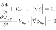
positive deposition-like direction and ![]() which should move in the negative etching-like direction. Figure 3.1
depicts such a scenario for a 500
which should move in the negative etching-like direction. Figure 3.1
depicts such a scenario for a 500![]() 500 geometry where the top surface moves at a rate of 0.25grid/time and the bottom surface
moves at a rate of -0.75grid/time for 10 time units. Therefore,
500 geometry where the top surface moves at a rate of 0.25grid/time and the bottom surface
moves at a rate of -0.75grid/time for 10 time units. Therefore,
![]() and
and
![]() is set and the LS equations
is set and the LS equations
 |
(88) |
|
When the initial geometry involves two level set interface systems
![]() and
and ![]() and the goal of the simulation is
to move them downward and upward, respectively, no interface splitting is required.
Only the separation of the two interfaces into two different LS systems is required. Therefore,
assuming the initial interface system
and the goal of the simulation is
to move them downward and upward, respectively, no interface splitting is required.
Only the separation of the two interfaces into two different LS systems is required. Therefore,
assuming the initial interface system ![]() , then we introduce a second LS system
, then we introduce a second LS system
![]() . The
top LS interface from
. The
top LS interface from ![]() is removed, while the bottom interface from
is removed, while the bottom interface from ![]() is also removed.
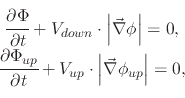
The two systems are now
separated as shown in Figure 3.2a and Figure 3.2b, respectively.
Figure 3.2c depicts the scenario after the following LS equations were processed for the individual
surfaces on a 500
is also removed.
The two systems are now
separated as shown in Figure 3.2a and Figure 3.2b, respectively.
Figure 3.2c depicts the scenario after the following LS equations were processed for the individual
surfaces on a 500![]() 500 geometry:
500 geometry:
 |
(89) |
|
When a mask layer is introduced into a system where a material is grown in such a way that two LS interfaces need to be
simultaneously moved in opposite directions, the mask layer influences the movement of both level sets. Therefore, when
the LS system is split, such as those from Figure 3.1 and Figure 3.2, the mask layer must
remain in both LS systems. Another aspect which must be considered is the manner in which the different LS interfaces are labeled.
This will be addressed in Section 3.2.2, while here only the initial separation of materials to form the two
LS systems will be described. Assuming we start with a LS description ![]() which includes two surfaces. One describes the location of
the mask and the second the location of the material which will be grown and is located below the mask. A second LS description
can now be initiated
which includes two surfaces. One describes the location of
the mask and the second the location of the material which will be grown and is located below the mask. A second LS description
can now be initiated ![]() , which only holds the mask LS from
, which only holds the mask LS from ![]() .
. ![]() contains
contains
![]() and
and
![]() and it is a simple matter of moving the desired interface by
and it is a simple matter of moving the desired interface by
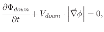 |
(90) |
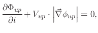 |
(91) |
|
![\includegraphics[width=0.315\linewidth]{chapter_oxidation_modeling/figures/OneLS_initial.eps}](img369.png)
![\includegraphics[width=0.315\linewidth]{chapter_oxidation_modeling/figures/OneLS_Phi2.eps}](img370.png)
![\includegraphics[width=0.315\linewidth]{chapter_oxidation_modeling/figures/OneLS_final.eps}](img371.png)
![\includegraphics[width=0.315\linewidth]{chapter_oxidation_modeling/figures/TwoLS_initial_Phi_down.eps}](img373.png)
![\includegraphics[width=0.315\linewidth]{chapter_oxidation_modeling/figures/TwoLS_initial_Phi.eps}](img374.png)
![\includegraphics[width=0.315\linewidth]{chapter_oxidation_modeling/figures/TwoLS_final.eps}](img375.png)
![\includegraphics[width=0.315\linewidth]{chapter_oxidation_modeling/figures/masked_mask.eps}](img381.png)
![\includegraphics[width=0.315\linewidth]{chapter_oxidation_modeling/figures/masked_down.eps}](img382.png)
![\includegraphics[width=0.315\linewidth]{chapter_oxidation_modeling/figures/masked_up.eps}](img383.png)