Next: 5.1.3 Modeling Interaction between Up: 5.1 Spray Pyrolysis Deposition Previous: 5.1.1 Modeling Droplet Atomization
Forces acting on the droplet can be used in order to calculate the location where the droplet should reach the surface. This is a challenge because the simulation environment must now be divided into several segments. For an in-depth explanation of the forces involved during the droplet transport, refer to Section 4.1.3. In this section, the modeling of those forces and the droplet movements will be described. The first segment we must treat separately is the thermal zone which is within 10mm of the wafer surface. In this area, the temperature gradient shown in Figure 4.5 is high and the thermal forces play a significant role in the droplet speed as well as size, due to evaporation. In addition, when the electrical force is included, the complexity of the problem is significantly increased.
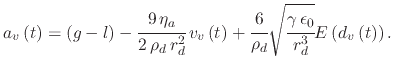
This section will first examine the droplet's motion with no influence from the electrical force outside of the thermal zone. Subsequently, the electrical force is introduced and its influence on the droplet motion is described. Finally, the thermal zone is covered by the introduction of the thermophoretic force and the idea of droplet evaporation. Figure 5.1 shows how the simulation space is divided in order to accommodate the thermal zone for droplets.
![\includegraphics[width=\linewidth]{chapter_process_modeling/figures/space.eps}](img601.png) |
For a more detailed explanation regarding the derivation of the motion equations used in this section, refer to app:transport.
In order to follow the trajectory of a droplet after leaving the atomizer and under the influence of gravity and the Stokes force, the distance required
to reach the thermal zone
![]() , the initial velocity
, the initial velocity ![]() are the droplet radius
are the droplet radius ![]() are known. The equations for the gravitational
force and the
Stokes force can be reformulated to equations for acceleration
are known. The equations for the gravitational
force and the
Stokes force can be reformulated to equations for acceleration
![]() which govern droplet movement. It is important to note that the vertical
motion must be calculated first in order to know how much time
which govern droplet movement. It is important to note that the vertical
motion must be calculated first in order to know how much time ![]() is required to reach the thermal zone. The time
is required to reach the thermal zone. The time ![]() is then used in order to calculate
how much radial distance the droplet underwent during its vertical ``fall''. For the sake of simplicity, the vertical acceleration, velocity, and distance
will be marked with a subscript
is then used in order to calculate
how much radial distance the droplet underwent during its vertical ``fall''. For the sake of simplicity, the vertical acceleration, velocity, and distance
will be marked with a subscript ![]() , while radial acceleration, velocity, and distance will be marked with a subscript
, while radial acceleration, velocity, and distance will be marked with a subscript ![]() in the equations that follow.
in the equations that follow.
Vertical trajectory:
Given the droplet mass (4.2), the force of gravity (4.3) and the Stokes force (4.7), the
vertical acceleration experienced by the particle is given by:
 |
(163) |
 |
(164) |
| (167) |
Radial trajectory:
In order to calculate the radial trajectory, the time ![]() , radius
, radius ![]() , and initial velocity
, and initial velocity ![]() must be known. Those parameters are
derived using the vertical trajectory discussion.
The force of gravity does not influence the radial movement of the droplet; therefore, only the Stokes force must be considered. The acceleration of the
droplet is defined as
must be known. Those parameters are
derived using the vertical trajectory discussion.
The force of gravity does not influence the radial movement of the droplet; therefore, only the Stokes force must be considered. The acceleration of the
droplet is defined as
| (169) |
 |
(170) |
As the droplet enters the heat zone, it experiences a large temperature gradient resulting from a rapid increase in temperature. This causes the droplet
to be exposed to an additional retardant force component, which pushes it away from the hot surface (4.9). This force is assumed to have a uniform
behavior throughout the heat zone, making it straightforwardly implemented in the previously-discussed trajectory calculations. The thermophoretic force
is independent of the droplet velocity, therefore it causes a reduction of the gravitational force effect. This is performed by replacing ![]() in
(5.3) to (5.7) with a value
in
(5.3) to (5.7) with a value
![]() , where
, where ![]() is the addition of the negative acceleration caused by the thermal gradient
is the addition of the negative acceleration caused by the thermal gradient
An additional effect which occurs in the heat zone is the significant increase in the mean droplet radius noticed in measurements [171]. The reason behind the increased mean radius is that droplets with a small radius evaporate before reaching the surface, while larger droplets, although also evaporating slightly, stay relatively complete until fully in contact with the surface [171]. Tracking of the detailed changing droplet size during its travel through the heat zone does not modify the model enough to merit the additional computational expense. Therefore, the model automatically excludes droplets which bounce away from the surface due to the thermophoretic force, while other droplets which reach the surface have their radius reduced as they enter the heat zone. The approximate relationship which governs the small droplet's lifetime is given by [81]
The exact solution for the decrease of the radius of a droplet requires the solution of a diffusion equation, since the evaporation of a droplet is given by [81]
 |
(175) |
| (176) |
 , while
When an ESD system is used for spray pyrolysis deposition, an electric field is introduced between the atomizing needle and the metal plate on which
the substrate is placed. This electric field provides additional acceleration for the droplets so that they do not need to rely only on the gravitational force,
as is the case for PSD systems. The addition of the electrical force to the equations which govern droplet motion is not as straight-forward as was the
case with the thermophoretic force, because the electric field which is generated in the experimental region is not uniform [228]. The
external electric field is calculated by representing the atomizer as a semi-infinite line of charge and the substrate as an infinite conducting plane, separated
by a distance ![]() . The equation governing the external electric field is given by [96]
. The equation governing the external electric field is given by [96]
 |
(181) |
![\includegraphics[width=0.7\linewidth]{chapter_process_modeling/figures/K_V.eps}](img668.png) |
The individual vertical and radial components of the electric field when taking the gradient of ![]() from (5.21) can be found
from (5.21) can be found
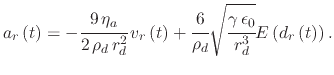
Figure 5.3 shows the value for the normalized potential
![]() and its distribution in an ESD deposition setup.
The atomizing nozzle is located at
and its distribution in an ESD deposition setup.
The atomizing nozzle is located at
![]() .
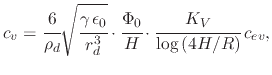
The inset shows the electric field distribution in the same simulation space. It is evident that the strength of the electric field is not uniform or linear, but
that the field causes charged droplets to spread radially.
.
The inset shows the electric field distribution in the same simulation space. It is evident that the strength of the electric field is not uniform or linear, but
that the field causes charged droplets to spread radially.
![\includegraphics[width=\linewidth]{chapter_process_modeling/figures/Efield4.eps}](img674.png) |
Given the electric field distribution shown in Figure 5.3 (inset), which is dependent on the droplet position, the electrical force (4.4) cannot be implemented to find the vertical displacement using an explicit function in the form (5.6) from the analysis where the droplet is affected only by the gravitational and Stokes forces. The vertical acceleration, when the electric field is considered is no longer (5.3), but it changes to
| (190) |
An explicit equation for the time required to achieve the displacement (5.32) cannot be found.
Therefore, the droplet motion must be solved by time discretization, MC methods, or iteratively in order
to obtain the droplet trajectory through the electric field. For the presented topography simulator, an iterative method is used to solve for
![]() with the initial guess
with the initial guess ![]() given by (5.7).
Since the introduction of the electric field causes the required time for a droplet
to reach the surface
given by (5.7).
Since the introduction of the electric field causes the required time for a droplet
to reach the surface ![]() to decrease, the time
to decrease, the time ![]() with the electrical force included must be
with the electrical force included must be
![]() .
For the purposes of a topography simulation, an assumption for a constant electric field is sufficient [171]. It is also important to note that
the full extent of the radial distance
.
For the purposes of a topography simulation, an assumption for a constant electric field is sufficient [171]. It is also important to note that
the full extent of the radial distance ![]() need not be incorporated in the linearization process. When considering the deposition on a chip which
extends 1mm radially from a spray source located at a vertical distance of 100mm, this means the radial distance
need not be incorporated in the linearization process. When considering the deposition on a chip which
extends 1mm radially from a spray source located at a vertical distance of 100mm, this means the radial distance
![]() is of importance.
Additional complexity may be introduced unnecessarily into the model leading to increased computational costs. The equations governing the electric
field are used in the simplified model in order to determine the initial direction of the droplet. The main effect from the electrical force is seen
directly as the droplet exits the nozzle. At this location, the droplet's initial speed and direction is decided.
is of importance.
Additional complexity may be introduced unnecessarily into the model leading to increased computational costs. The equations governing the electric
field are used in the simplified model in order to determine the initial direction of the droplet. The main effect from the electrical force is seen
directly as the droplet exits the nozzle. At this location, the droplet's initial speed and direction is decided.
![$\displaystyle t=\cfrac{gW\left[\cfrac{\left(g-s\,v_{v0}\right)\cdot e^{1-\cfrac...
...\right)\right)}{g}}}{g}\right]-
g+s\,v_{v0}+s^{2}\left(H-t_{th}\right)}{g\,s},$](img616.png)
![$\displaystyle \Phi^{*}\left(r^*,z^*\right)=\cfrac{K_{V}}{\log\left(4H\slash R\r...
...(1-z^*\right)}{\sqrt{r^{*2}+\left(1+z^*\right)^{2}}+\left(1+z^*\right)}\right],$](img660.png)
![$\displaystyle \cfrac{\delta\Phi^*}{\delta z^*}=-\cfrac{K_{V}}{\log\left(4H\slas...
...t(1+z^{*}\right)^{2}}}+\cfrac{1}{\sqrt{r^{*2}+\left(1-z^{*}\right)^{2}}}\right]$](img670.png)
![$\displaystyle \cfrac{\delta\Phi^*}{\delta r^{*}}=\cfrac{K_{V}}{r^*\log\left(4H\...
...*}\right)^{2}}}-\cfrac{1-z^{*}}{\sqrt{r^{*2}+\left(1-z^{*}\right)^{2}}}\right].$](img671.png)
![$\displaystyle c_{ev}\cdot z^{*}\approx\left[\cfrac{1}{r^{*2}+\left(1+z^{*2}\right)}+\cfrac{1}{r^{*2}+\left(1-z^{*2}\right)}\right].$](img680.png)