|
|
|
|
Previous: 4.3 Anomalous Output Characteristic Up: 4. Standard Energy Transport Simulations Next: 4.5 Cause of the Effect |
|
|
|
|
Previous: 4.3 Anomalous Output Characteristic Up: 4. Standard Energy Transport Simulations Next: 4.5 Cause of the Effect |
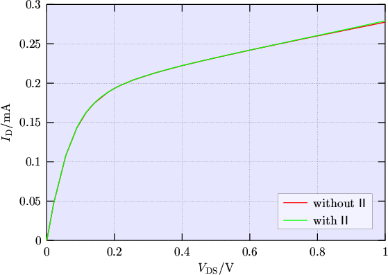 |
The kink in the drain current does not appear because both contributing effects are suppressed, namely the body effect and the amplification of the impact-ionization current through the bipolar effect. As expected, a positive output conductance is obtained.
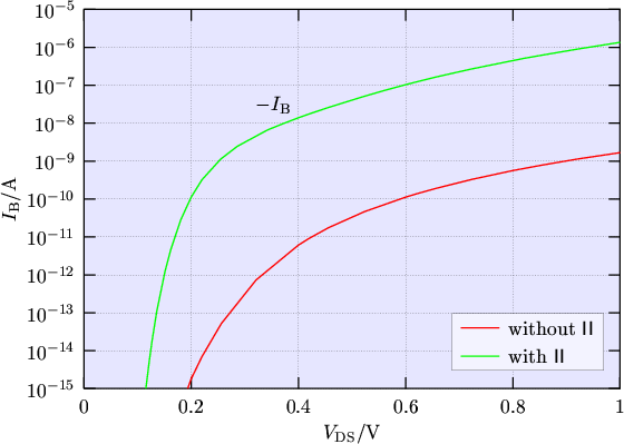
The strong influence of impact-ionization can be seen in the corresponding bulk currents
(Fig. 4.7). With impact-ionization included the expected result of a body current
flowing out of the transistor is obtained (
![]() ). But if in contrast impact-ionization is
neglected there is a body current flowing into the device (
). But if in contrast impact-ionization is
neglected there is a body current flowing into the device (
![]() ), which is
several orders of magnitude smaller. It is to note that the real substrate current due to
impact-ionization has the opposite sign. The situation of a positive substrate current shows that even in
this bulk MOSFET hot electron diffusion into the p-body occurs. Note that this is a
prediction of the energy transport model only, and is not confirmed by experimental data.
), which is
several orders of magnitude smaller. It is to note that the real substrate current due to
impact-ionization has the opposite sign. The situation of a positive substrate current shows that even in
this bulk MOSFET hot electron diffusion into the p-body occurs. Note that this is a
prediction of the energy transport model only, and is not confirmed by experimental data.
 |
To estimate if the resulting drain current obtained by the drift-diffusion simulation using impact-ionization shown
in Fig. 4.2 is really caused by the increased body potential, simulations using
the same transistor but with a body contact applied (Device 2) were made. The results are
shown in Fig. 4.8 where the curve from Fig. 4.2 which used
impact-ionization is depicted again--this time the full
![]() range is shown.
range is shown.
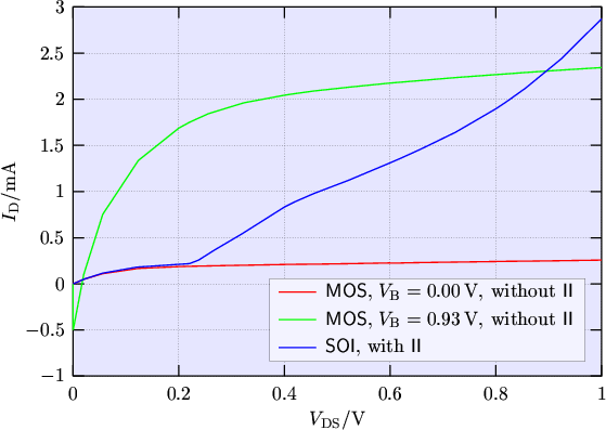 |
From Fig. 4.3 it can be seen that the body potential is shifted from
![]() at
at
![]() to
to
![]() at
at
![]() resulting in a total shift of
resulting in a total shift of
![]() . This
voltage is now applied at the body contact of Device 2. In this case the source-body diode
(and at small
. This
voltage is now applied at the body contact of Device 2. In this case the source-body diode
(and at small
![]() even the drain-body diode) is biased in forward direction
yielding a negative drain current of
even the drain-body diode) is biased in forward direction
yielding a negative drain current of
![]() at
at
![]() . Accounting for this negative current offset total agreement with the curve
using impact-ionization is obtained at
. Accounting for this negative current offset total agreement with the curve
using impact-ionization is obtained at
![]() .
.
M. Gritsch: Numerical Modeling of Silicon-on-Insulator MOSFETs PDF