In order to derive the expressions for the extraction of fixed oxide charge we
assume that no interface states are generated while stressing:  , as
well as
, as
well as  are the same before and after stress, while build-up
of
are the same before and after stress, while build-up
of  occurs in time. These conditions are only roughly satisfied
for stress at low
occurs in time. These conditions are only roughly satisfied
for stress at low  (hole injection only) and probably also for stress
at high (electron injection only) in
(hole injection only) and probably also for stress
at high (electron injection only) in  -channel MOSFETs. They are
better fulfilled in
-channel MOSFETs. They are
better fulfilled in  -channel devices for stress at low and medium
(electron injection).
-channel devices for stress at low and medium
(electron injection).
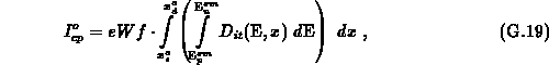
The charge-pumping current before stress  is given by
with  and
and  being the boundaries for the total capture of holes
in a virgin MOSFET. In a symmetric device,
being the boundaries for the total capture of holes
in a virgin MOSFET. In a symmetric device,  holds. A
step-approximation is assumed for the
transition between the total capture and the zero capture areas. For the
charge-pumping technique we chose the constant amplitude method, discussed in
Section 3.5.2. In this technique
holds. A
step-approximation is assumed for the
transition between the total capture and the zero capture areas. For the
charge-pumping technique we chose the constant amplitude method, discussed in
Section 3.5.2. In this technique  is variable,
while
is variable,
while  is constant.
  and
and  vary along the
interface due to doping, but do not change with during the course of
experiment. Therefore, emission times
vary along the
interface due to doping, but do not change with during the course of
experiment. Therefore, emission times  and
and  and
emission levels
and
emission levels  and
and  vary along the
 -coordinate, but remain constant during the course of experiment, as well.
We adopt that
-coordinate, but remain constant during the course of experiment, as well.
We adopt that  and
and  are spatially
uniform.
are spatially
uniform.
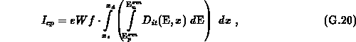
After stress the charge-pumping current reads
where  and
and  are the capture boundaries after the stress. The impact
of
are the capture boundaries after the stress. The impact
of  on the local surface potential is nearly the same before and after
the stress (generally negligible in practice). The stress-generated
on the local surface potential is nearly the same before and after
the stress (generally negligible in practice). The stress-generated
 changes the local
  and
and  . The difference
in the measured current becomes
. The difference
in the measured current becomes 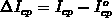 .
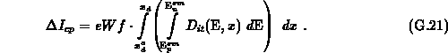
We will derive a general expression, valid for an arbitrarily large
.
We will derive a general expression, valid for an arbitrarily large  ,
but with the restriction that only one value
,
but with the restriction that only one value  exists for each
  . The assumption that the stress does not
change the conditions at the source side
. The assumption that the stress does not
change the conditions at the source side  is introduced. Since
fixed charge roughly induces the same local shift in ,
,
is introduced. Since
fixed charge roughly induces the same local shift in ,
,  and
and 
 the emission times and consequently, the
emission levels
the emission times and consequently, the
emission levels  and
and  remain unchanged
after the stress. Remember that they also do not change by varying in
this charge-pumping technique. It follows
remain unchanged
after the stress. Remember that they also do not change by varying in
this charge-pumping technique. It follows
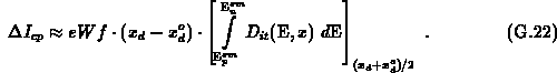
and , as well as  and
and  vary
moderately within the short interval from to . The emission levels
vary
moderately within the short interval from to . The emission levels
 and
and  change only slightly in this interval
because of their logarithmic dependence on the emission times.
Therefore, G.21 may well be approximated by
change only slightly in this interval
because of their logarithmic dependence on the emission times.
Therefore, G.21 may well be approximated by
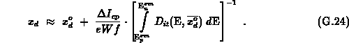
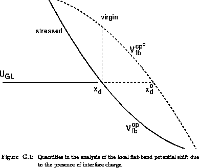
The local interface charge at can be calculated by
In relationship G.23,  is the charge-pumping
flat-band potential in the virgin device at and
is the charge-pumping
flat-band potential in the virgin device at and  is the
charge-pumping flat-band potential at the same position , but after the
stress. A positive charge lowers the local , as consistent
with G.23. When applying the constant-pulse method we scan the
interface by while keeping the top level
is the
charge-pumping flat-band potential at the same position , but after the
stress. A positive charge lowers the local , as consistent
with G.23. When applying the constant-pulse method we scan the
interface by while keeping the top level  sufficiently high so
that the interface is inverted in complete. At the critical coordinate ,
sufficiently high so
that the interface is inverted in complete. At the critical coordinate ,
 holds.
The charge extracted from relationship G.23 will be
smaller than the charge actually inducing the local potential shift. Being
aware of this fact we may call the extracted to be the apparent
interface charge. Differences between the apparent and the real charge are
addressed in Appendix F.
From G.22 follows that the coordinate actually scanned is given by
If the impurity concentration is known along the interface,
is known as well. To find the second quantity
in G.23, i.e. which is necessary to
calculate , one should observe that
 holds. This relationship is
illustrated in Figure G.1. Simple replacements lead to
holds. This relationship is
illustrated in Figure G.1. Simple replacements lead to
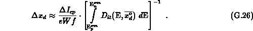
where the spatial shift is given by
For a low density of , the shift  is small
and G.25 reduces to
is small
and G.25 reduces to
Before applying G.25 on the experimental data, the spatial
distribution  must be known for the virgin device. This
distribution can be calculated by a simple two-dimensional numerical simulation.
The critical concentration
must be known for the virgin device. This
distribution can be calculated by a simple two-dimensional numerical simulation.
The critical concentration  which depends on the bottom level
duration
which depends on the bottom level
duration  , is the input to the calculation. The differential current
 is measured. For given , the results
from the known inverse relationship. The follows
from G.26. Using G.25, the can be
calculated. The only unknown factor is
is measured. For given , the results
from the known inverse relationship. The follows
from G.26. Using G.25, the can be
calculated. The only unknown factor is  . If
is uniform in the channel, this factor may be considered as roughly constant
along the whole channel, which enables an estimation
. If
is uniform in the channel, this factor may be considered as roughly constant
along the whole channel, which enables an estimation
In G.28, is the current before stress and
 is the effective charge-pumping channel
length.
is the effective charge-pumping channel
length.
Note that also for a uniform distribution, the factor
is different for traps around the drain/bulk junction
than for traps in the middle of the channel. This difference introduces a
proportional error in the determination of . The error is, however,
small. A better approach than using G.28 is to extract the spatial
distribution of in the virgin device by the methods
given in the first part of this appendix. This distribution can be directly
employed in G.26.
This method for the extraction of fixed oxide charge is sensitive to errors
in the gradient of the charge-pumping flat-band potential distribution, as is
evident from G.27. Therefore, the doping profile must be known
with sufficient accuracy in the region of interest (gate/drain overlap region;
around the junction). This is a serious limitation to the method. However, an
inspection of the literature shows that only few attempts to extract
in MOSFETs have been proposed [480][78]. The approach
in [78][74] relies on observing the
 versus
  characteristics and can only provide a qualitative estimation of .
A study based on the numerical calculation is necessary to evaluate the potential of the present method to extract fixed charge distribution, as is done for interface charge in Section 3.5.2.