5.5 Analysis of the OFIT Technique
As described in [95, 96], a constant base-level CP measurement with
 is performed using a gradually increasing pulse amplitude
  .
Until the desired stress level is reached, starting from
.
Until the desired stress level is reached, starting from  down to
  ,
the pulse slopes have to be kept constant to obtain comparable results. Constant
pulse slopes ensure that the upper and lower energy boundaries of the active
energy interval remain unchanged when
,
the pulse slopes have to be kept constant to obtain comparable results. Constant
pulse slopes ensure that the upper and lower energy boundaries of the active
energy interval remain unchanged when  increases [50]. Due to a
constant pulse slope the amplitude of
increases [50]. Due to a
constant pulse slope the amplitude of  is proportional to the pulse
rising (often referred to as leading) and falling (trailing) time. Given the
additional requirement of a constant duty cycle, the rise and fall times
have to be adapted at every voltage step within the CP measurement to
obtain the proper charge pumping current
is proportional to the pulse
rising (often referred to as leading) and falling (trailing) time. Given the
additional requirement of a constant duty cycle, the rise and fall times
have to be adapted at every voltage step within the CP measurement to
obtain the proper charge pumping current  . Since it is inevitable to
change both the pulse width and also the rise and fall times one has to
ask for the potential pitfalls: Are OFIT-data obtained during stress and
relaxation comparable? If that is not the case, is there some possibility to
correct this nonconformity? These questions will be examined in the
following.
. Since it is inevitable to
change both the pulse width and also the rise and fall times one has to
ask for the potential pitfalls: Are OFIT-data obtained during stress and
relaxation comparable? If that is not the case, is there some possibility to
correct this nonconformity? These questions will be examined in the
following.
Starting with Fig. 5.13 the two large arrows pointing up and down reveal
some important aspects of the temporal evolution of the pulses during a CP
measurement. The charge pumping current  at stress conditions
(
at stress conditions
( ) differs a lot when compared to that obtained during relaxation
(
) differs a lot when compared to that obtained during relaxation
( ). The higher the NBTI stress conditions, the larger the
 -signal becomes. This can be partly attributed to the desired effect of using
the measurement setup to also stress the device. However, it cannot fully account
for the observed behavior.
-signal becomes. This can be partly attributed to the desired effect of using
the measurement setup to also stress the device. However, it cannot fully account
for the observed behavior.
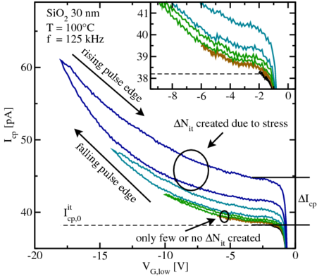
 for different pulse amplitudes
as observed in constant base-level CP measurements with
for different pulse amplitudes
as observed in constant base-level CP measurements with  and a gradually increasing pulse amplitude
  from
from
 down to
  .
.  shows a significant
hysteresis. If
shows a significant
hysteresis. If  is evaluated at the falling pulse edge, the lower branch of
the curve is traversed. Evaluation of the rising pulse edges gives the upper
branch. However, the contribution of slow oxide states and an additional
hysteresis (marked with
is evaluated at the falling pulse edge, the lower branch of
the curve is traversed. Evaluation of the rising pulse edges gives the upper
branch. However, the contribution of slow oxide states and an additional
hysteresis (marked with  ) are clearly visible for increasing pulse
amplitudes. This implies that depending on the pulse amplitude,
) are clearly visible for increasing pulse
amplitudes. This implies that depending on the pulse amplitude,  will
contain contributions of both, interface and oxide states. Provided only
interface states are available,
will
contain contributions of both, interface and oxide states. Provided only
interface states are available,  should be independent of the pulse
amplitude (dashed line of
should be independent of the pulse
amplitude (dashed line of  ).
).