
To improve the measurement resolution of  , Reisinger et al. developed a
fast
, Reisinger et al. developed a
fast  -method [11], which is depicted in Fig. 2.2. It distinguishes
two modes of operation: During the measurement-mode a constant and
device-specific drain current
-method [11], which is depicted in Fig. 2.2. It distinguishes
two modes of operation: During the measurement-mode a constant and
device-specific drain current  serves as “threshold current”
 -criterium.2
This is achieved by a feedback loop using an operating amplifier. Simultaneously,
the resulting corresponding threshold voltage
-criterium.2
This is achieved by a feedback loop using an operating amplifier. Simultaneously,
the resulting corresponding threshold voltage  of the device is recorded.
(The initial reference
of the device is recorded.
(The initial reference  has to be measured in advance.) When switching to
the stress-mode all contacts but the gate are grounded, the latter being set to
has to be measured in advance.) When switching to
the stress-mode all contacts but the gate are grounded, the latter being set to
 .
.
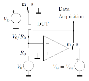
 -method after Reisinger et al. [11]. When switched to
the measurement-mode ‘m’ the drain current of the device under test (DUT)
is forced to a constant (
-method after Reisinger et al. [11]. When switched to
the measurement-mode ‘m’ the drain current of the device under test (DUT)
is forced to a constant ( ) by the feedback loop of the operating
amplifier. At the same time the threshold voltage
) by the feedback loop of the operating
amplifier. At the same time the threshold voltage  is measured. When
switched to the stress-mode ‘s’, source and drain are grounded and only the
gate is set to
is measured. When
switched to the stress-mode ‘s’, source and drain are grounded and only the
gate is set to  . The switching between the two modes is done by
fast electronic switches.
. The switching between the two modes is done by
fast electronic switches.
With the fast- -method a measurement delay of
  has been
achieved, equivalent to the settling time of the feedback loop. Compared to the
studies of Rangan et al. [14], who only use off-the-shelf equipment, this results in
a three decades faster read-out speed.
has been
achieved, equivalent to the settling time of the feedback loop. Compared to the
studies of Rangan et al. [14], who only use off-the-shelf equipment, this results in
a three decades faster read-out speed.