

 Previous: 4.4.1.1 Collision Partner in
Up: 4.4.1 Selection of Collision
Next: 4.4.2 Nuclear Stopping Process
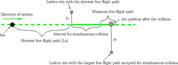
Figure 4.5:
Schematic figure for the selection of collision partners for
simultaneous collisions in crystalline materials.
 |
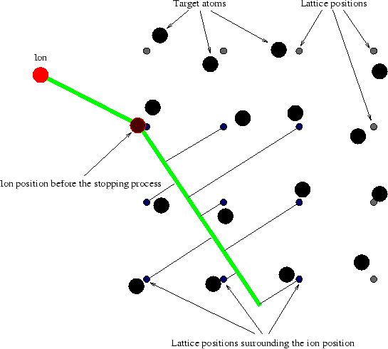
Figure 4.6:
Schematic figure for the selection of collision partners in crystalline materials.
 |
In crystalline materials the cores of the target are placed around crystal lattice
positions. The collision partner is determined by looking for a
lattice position in the direction of motion, considering the following criteria
[35]:
- Lattice sites with a distance smaller than the search distance to
the current ion position are selected (small blue circles in
Fig. 4.6). The search distance has a default value of
three times the lattice constant as suggested in [30].
- Several criteria are applied to remove selected
lattice sites from this initial list:
- The lattice site is located opposite to the direction of motion, because
an ion cannot collide with an atom opposite to the direction of motion.
- The free flight path (projection of the vector from the ion position to
the lattice site position on the vector of the direction of motion) is shorter
than the minimum free flight path which is set to five percent of the
lattice constant.
- The free flight path is larger than the maximum free flight path
which is 95% of the lattice constant.
- The impact parameter (distance from the vector of the direction of
motion) is larger than the maximum impact parameter which has a default
value of the size of the lattice constant.
- The distance between the current ion position and the lattice site is
smaller than the minimum distance which is 15% of the lattice constant.
- Collision partners which have been involved in the previous collision are
removed from the list to avoid multiply treating a collision partner. This check
is only performed if the scattering angle falls below the minimum scattering angle
 which has a default
value of 30
 .
.
This list of criteria and the default values of the parameters used in the
criteria are suggested in [30], to optimize the performance of the
simulation, to avoid a skipping of collision events, to avoid multiply treating
the same collision partner and to avoid placing collision partners unphysically
close to each other. Up to now the influence of these effects
on the simulation results has not been investigated rigorously. Therefore it is
not possible to estimate the error which would arises from neglecting these
effects.
- The remaining lattice positions are ordered by the free flight path. From
this list all lattice sites are accepted as collision partners whose free flight
path do not differ more than the interval for simultaneous collisions
from the shortest free flight path in the list. Additionally lattice sites are
considered with a flight path difference less than the minimum free
flight path from the longest flight path according to previous condition
(Fig. 4.5). An interval for simultaneous collisions of 10% of
the lattice constant is suggested in [30].
- The actual collision partners are placed randomly in a plane perpendicular
to the direction of motion, which contains the lattice position. A Gaussian
probability distribution function is assumed. Thereby the thermal vibration of
the atoms is considered (Sec. 3.3.4). The vibration amplitude
is a user defined parameter (command-line parameter atomVibration), which should
be set according to the average wafer temperature during the implantation.
As a result of this procedure more than one collision partner can be selected
and therefore several nuclear collision events sometimes have to be calculated
simultaneously, while each of these collisions is treated as a binary collision
event. Simultaneous collisions are not an approximation to a multi-particle
interaction, but are used to avoid the skipping of collision events,
especially if an ion moves along the center of a crystalline channel, where at
least two lattice sites can be characterized approximately by the same criteria
in the selection procedure mentioned above. Without multiple collisions the
above selection criteria could result in skipping one of these potential
collision partners. The free flight path for a simultaneous collision is the
largest free flight path to one of the accepted collision partners.
Footnotes
- ... angle

- The minimum scattering angle can
be set by the command-line parameter minScatteringAngle


 Previous: 4.4.1.1 Collision Partner in
Up: 4.4.1 Selection of Collision
Next: 4.4.2 Nuclear Stopping Process
A. Hoessiger: Simulation of Ion Implantation for ULSI Technology

