 |
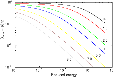
For the simulation of the nuclear stopping process it is assumed that the scattering process can be described by its asymptotic behavior. Therefore neither the position of the ion nor the position of the target atoms is changed. Just the momentum vectors of the particles are modified. Before the scattering event the ion is placed at the closest distance to the collision partner, which is equal to the impact parameter. In reality the minimum distance between the collision partners is larger than the impact parameter as shown in Fig. 4.7. According to Fig. 4.7 the error in the particle distance is low (below 10%) as long as the particle energy and the impact parameter are not too low. At the moment it is not possible to quantify the influence of the error in the particle distance on the simulation result. Therefore a rigorous treatment of the scattering process had to be implemented in the simulator, to be able to compare simulation results obtained by applying a rigorous treatment to simulation results generated by applying the asymptotic approximation.
 |
The asymptotic scattering process is implemented by a table based representation
of the scattering process ![]() as described by (3.88),
(3.89) and (3.90). A
bicubic spline interpolation is performed in between. The tabulated scattering
function is plotted Fig. 4.8.
as described by (3.88),
(3.89) and (3.90). A
bicubic spline interpolation is performed in between. The tabulated scattering
function is plotted Fig. 4.8.
Knowing the scattering angle in the center-of mass system, the scattering angles of the incident particle and of the recoil are calculated by (3.73) and (3.74) for the laboratory system and the energy transfer to the target atom is determined by (3.75).