For the phonon modes, the dynamic matrix is constructed using the fourth nearest-neighbor force constant model [83]. The force constant method uses a set of empirical fitting parameters and can be easily calibrated to experimental data. The fitting parameters given in Ref. [42] are used for graphene-based structures. Here, it is assumed that this model is still valid for structures that include ELDs. Although verification of its validity for ELD-ZGNRs has not been demonstrated yet, for instance using first-principle calculations, in Ref. [95] it was shown using DFT simulations that there is little difference between the phonon transmission of carbon nanotube structures with and without ELDs which could justify the model employed here. In any case, as shown below, the main influence on the phonon transport in this work originates from edge roughness scattering, which reduces the phonon transmission drastically. The effect of edge roughness scattering can be captured adequately by the model employed in this work. The influence of the ELDs on the phonon transmission is much smaller than the effect of edge roughness, and therefore usage of the numerically less expensive fourth nearest-neighbor force constant method is justified.
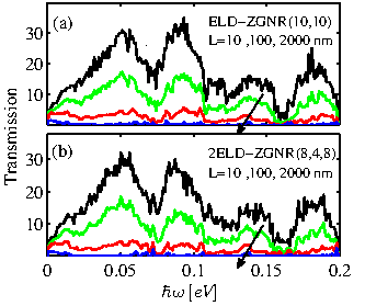
The phonon transmission for the edge roughened ELD-ZGNR(10,10)
channel versus energy is shown in Fig. 3.25-a. Results
for channel lengths ![]() ,
, ![]() , and
, and
![]() are shown. As
expected, the transmission decreases as the length is increased. What
is important, however, is that the decrease is much stronger than the
decrease of the electron transmission shown in
Fig. 3.23-a. For example, for a channel length of
are shown. As
expected, the transmission decreases as the length is increased. What
is important, however, is that the decrease is much stronger than the
decrease of the electron transmission shown in
Fig. 3.23-a. For example, for a channel length of
![]() the phonon transmission reduces by more than a factor of
the phonon transmission reduces by more than a factor of
![]() , whereas the electronic transmission even at larger length
, whereas the electronic transmission even at larger length
![]() reduces only by
reduces only by ![]() . Interestingly, the same
order of reduction of the phonon transmission is observed for the
2ELD-ZGNRs as shown in Fig. 3.25-b, indicating that the
line defect does not affect phonon conduction significantly compared to the effect of edge roughness.
. Interestingly, the same
order of reduction of the phonon transmission is observed for the
2ELD-ZGNRs as shown in Fig. 3.25-b, indicating that the
line defect does not affect phonon conduction significantly compared to the effect of edge roughness.
|
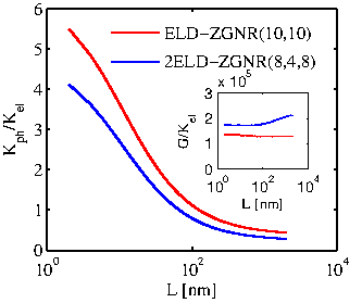
The denominator of the ![]() figure of merit consists of the sum
of the contributions to the thermal conductivity of the electronic
system and the phononic system. In graphene the phonon part dominates
the thermal conductivity, whereas the electronic part contribution is
much smaller. The situation is different, however, in rough ELD-ZGNRs,
in which the phonon thermal conductivity is degraded more than the
electronic thermal conductivity. Figure 3.26
clearly illustrates this effect by showing the ratio of the phonon
thermal conductance to the electronic thermal conductance versus the
rough channel length. The cases of ELD-ZGNR(10,10) and
2ELD-ZGNR(8,4,8) are shown in dashed-red and dash-dot-blue lines,
respectively. For small channel lengths, where transport is
quasi-ballistic and roughness does not affect the transmission
significantly,
figure of merit consists of the sum
of the contributions to the thermal conductivity of the electronic
system and the phononic system. In graphene the phonon part dominates
the thermal conductivity, whereas the electronic part contribution is
much smaller. The situation is different, however, in rough ELD-ZGNRs,
in which the phonon thermal conductivity is degraded more than the
electronic thermal conductivity. Figure 3.26
clearly illustrates this effect by showing the ratio of the phonon
thermal conductance to the electronic thermal conductance versus the
rough channel length. The cases of ELD-ZGNR(10,10) and
2ELD-ZGNR(8,4,8) are shown in dashed-red and dash-dot-blue lines,
respectively. For small channel lengths, where transport is
quasi-ballistic and roughness does not affect the transmission
significantly,
![]() is almost
is almost ![]() larger than
larger than
![]() . As the length of the channel increases and the
effect of the roughness becomes significant, the phonon system is
degraded more than the electronic system, and the
. As the length of the channel increases and the
effect of the roughness becomes significant, the phonon system is
degraded more than the electronic system, and the
![]() is significantly reduced compared to
is significantly reduced compared to
![]() . For lengths
. For lengths
![]() and beyond,
and beyond,
![]() can become even smaller than
can become even smaller than
![]() . The trend is the same when considering channels
with one or two ELDs.
. The trend is the same when considering channels
with one or two ELDs.
|
The inset of
Fig. 3.26 shows that the ratio of the electrical
conductance ![]() over
over
![]() is almost constant, from which it can be
indicated that both
is almost constant, from which it can be
indicated that both ![]() and
and
![]() follow the same
trend, as dictated by the Wiedemann-Franz law. The
follow the same
trend, as dictated by the Wiedemann-Franz law. The
![]() and
and
![]() values used in
Fig. 3.25 are extracted using the corresponding mean free
paths (MFPs) for phonons and electrons respectively, defined as Eq. 3.2. Alternatively,
values used in
Fig. 3.25 are extracted using the corresponding mean free
paths (MFPs) for phonons and electrons respectively, defined as Eq. 3.2. Alternatively,
![]() and
and
![]() could be extracted
from the transmission calculations by using a statistical average over
several rough samples for each channel length. The results of both
methodologies are in good agreement for the electronic part of the
thermal conductivity. For the lattice part, the agreement is good only
for the shorter channels, below
could be extracted
from the transmission calculations by using a statistical average over
several rough samples for each channel length. The results of both
methodologies are in good agreement for the electronic part of the
thermal conductivity. For the lattice part, the agreement is good only
for the shorter channels, below
![]() . For larger channel
lengths, the phonon transmission is severely reduced which increases
the relative statistical error in the calculation for extracting the
. For larger channel
lengths, the phonon transmission is severely reduced which increases
the relative statistical error in the calculation for extracting the
![]() . The values extracted directly from the
integration of the average phonon transmission might be as much as
. The values extracted directly from the
integration of the average phonon transmission might be as much as ![]() larger. In this case the ratio
larger. In this case the ratio
![]() will be closer to unity, but
this is still a huge advantage compared to devices without roughness.
will be closer to unity, but
this is still a huge advantage compared to devices without roughness.