Thermoelectric phenomena in materials can be described through three thermoelectric
effects, the Seebeck effect, the Peltier effect, and the Thomson effect. The Seebeck effect,
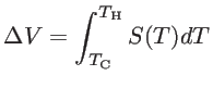
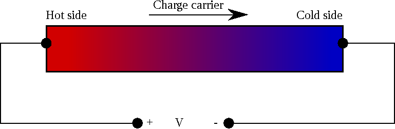
discovered in 1821 by Thomas Johann Seebeck [2], represents the generation of an electromotive force by a temperature gradient. When a temperature gradient is applied along a conductive material, charge carriers move from the hot to the cold side. In the
case of open-circuit, charge accumulation results in an electric potential difference, as
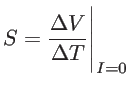
shown in Fig. 1.2. The Seebeck coefficient ![]() of a material shows the magnitude of the induced voltage in response to the temperature difference:
of a material shows the magnitude of the induced voltage in response to the temperature difference:
 |
(1.1) |
 |
(1.2) |
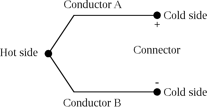
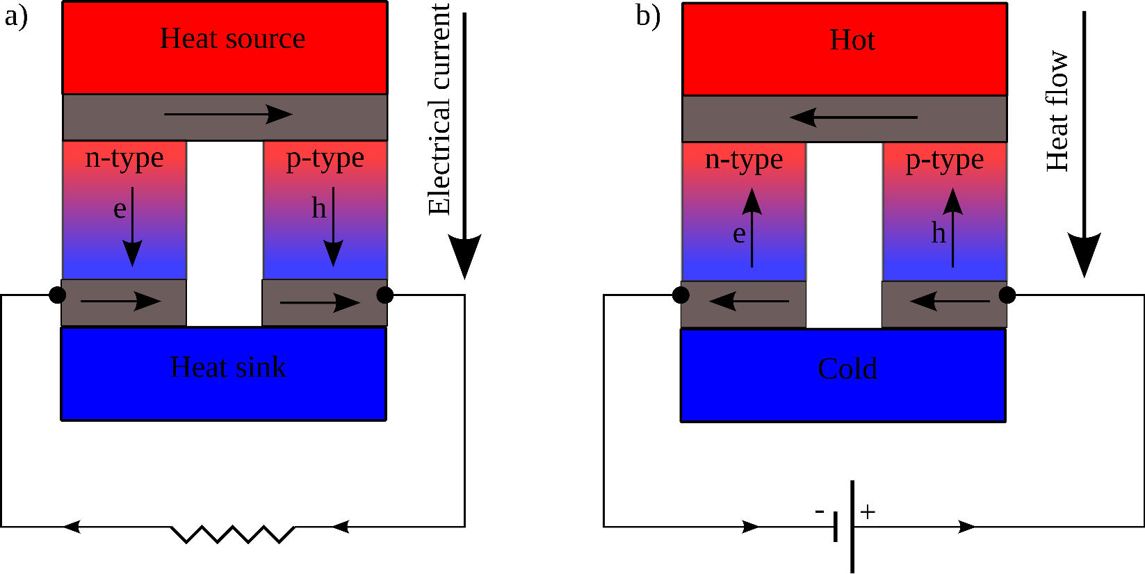
A single thermoelectric conductor, however, is not able to play the role of a battery. This is due to the fact that the net loop voltage would be zero if circuit wires of the same conductor were connected. A non-zero loop voltage can be obtained when two dissimilar conductors are connected in the configuration shown in Fig. 1.3. The circuit configuration of a thermoelectric generator is shown in Fig. 1.4-a. Here the generator is composed of two materials, an ![]() -type and a
-type and a ![]() -type material. The voltage obtained from this configuration is:
-type material. The voltage obtained from this configuration is:
| (1.3) |
where ![]() and
and ![]() are the Seebeck coefficients of the
are the Seebeck coefficients of the ![]() -type and
-type and ![]() -type materials,
respectively, and
-type materials,
respectively, and ![]() is the Seebeck coefficient of the device (junction). The
Seebeck coefficient of a
is the Seebeck coefficient of the device (junction). The
Seebeck coefficient of a ![]() -type material is positive, that of an
-type material is positive, that of an ![]() -type material negative. Therefore, using this configuration one can achieve a high net voltage.
-type material negative. Therefore, using this configuration one can achieve a high net voltage.
|
The Peltier effect, on the other hand, discovered by Athanaseal Jean Charles Peltier
in 1834, describes how an electrical current can create a heat flow. This effect has
enabled the second application of thermoelectric devices, the thermoelectric cooler, as
shown in Fig. 1.4-b. Here, by applying an external power source, both the electrons of the ![]() -type conductor and the holes of the
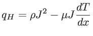
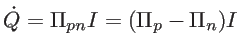
-type conductor and the holes of the ![]() -type conductor move and carry heat from one side to the other. Therefore, one side cools down, whereas the other side heats up. The heat flow absorbed at the hot side is proportional to the current through the junction:
-type conductor move and carry heat from one side to the other. Therefore, one side cools down, whereas the other side heats up. The heat flow absorbed at the hot side is proportional to the current through the junction:
 |
(1.4) |
The Thomson effect, observed by William Thomson in 1851, expresses a relation for heat production in a current-carrying conductor in the presence of temperature gradient:
According to the Thomson relations, these three thermoelectric coefficients are not independent. The Peltier coefficient and the Seebeck coefficient are linearly related to each other [3]
| (1.6) |
 |
(1.7) |