Next: D. Nonplanar Material Interface
Up: C. Stratified Medium
Previous: Propagation Matrix
In the preceding section we have presented a powerful formalism to analyze
the field propagation phenomenon within one homogeneous planar layer.
The results are now extended to a stack of such homogeneous planar layers
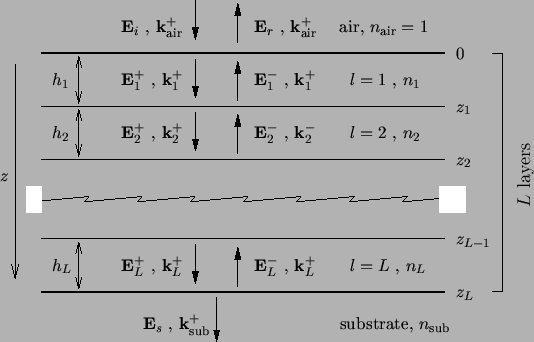
as shown in the schematic of Figure C.2.
Onto the medium a plane wave with amplitude
Ei is incident.
Due to the different refraction indices a wave
Er
is reflected. At the bottom only an outgoing wave
Es leaves the
stack traveling into the infinitely extended substrate.
Inside the stack within each of the
L layers two waves propagating downwards and upwards,
El+
and
El-, respectively, occur.
The height of one layer is denoted by hl,
the interfaces are located at zl, and the refraction index of
the layer materials is nl.
Figure C.2:
A stratified medium consists of a
stack of
homogeneous planar layers. Above we have an incident and a reflected wave,
Ei and
Er, respectively, below only an outgoing wave
Es travels into the infinitely extended substrate, and in
between the waves
E+l and
E-l travel downwards and
upwards the L layers.
|
|
We start with the description of the boundary conditions valid at any interface
between two adjacent layers l - 1 and l. Elementary results of EM theory
postulates that in the absence
of a surface current density both the tangential electric and tangential
magnetic field components are continuous across the
surface [11, p. 6]. Hence we obtain in our notation at any
interface position zl - 1
 |
(C.20) |
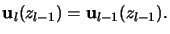
Using the relation (C.19) yields the lateral field components
at the next interface located at
zl = zl - 1 + hl
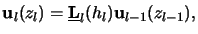 |
(C.21) |
whereby
 is the propagation matrix of layer l.
This relation is of fundamental importance as it propagates the field
from one interface to the next. Now a recursive evaluation connects the
lateral field components at any vertical position z to
the field occurring on top of the interface at z = 0 by
is the propagation matrix of layer l.
This relation is of fundamental importance as it propagates the field
from one interface to the next. Now a recursive evaluation connects the
lateral field components at any vertical position z to
the field occurring on top of the interface at z = 0 by
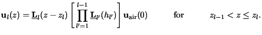 |
(C.22) |
At the interface to the substrate, i.e., at the bottom
zL of the stack, we thus obtain
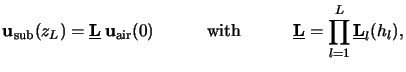 |
(C.23) |
whereby
 is simply called the propagation matrix of the
stratified
medium. Obviously the lateral field components at the top and at the
bottom of the stack are related by this equation.
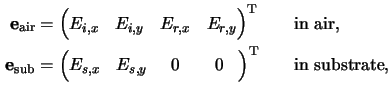
Thus also the wave amplitudes occurring in the air and in the substrate
can be related. From (C.19) and (C.14)
we obtain
uair(h) =
is simply called the propagation matrix of the
stratified
medium. Obviously the lateral field components at the top and at the
bottom of the stack are related by this equation.
Thus also the wave amplitudes occurring in the air and in the substrate
can be related. From (C.19) and (C.14)
we obtain
uair(h) =  eair and
usub(h) =
eair and
usub(h) =  esub and
the relation looked for writes to
esub and
the relation looked for writes to
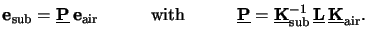 |
(C.24) |
Finally, we again leave off the matrix-vector notation used so far to account
for the physical situation depicted in Figure C.2. As can be
seen the two amplitude vectors
eair and
esub are given by (cf. (C.9))
because in the substrate only outgoing light has to be considered.
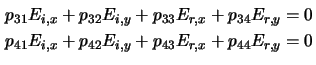
By explicitly writing the third and fourth rows of the matrix equation
(C.26) we obtain the two necessary conditions
that have to be satisfied by the incoming and the reflected light
Ei and
Er, respectively.
These two equations relate the lateral components of the field amplitudes
occurring above the stack. They establish the boundary conditions needed
for the differential method in case of multiple planar homogeneous layers
below the simulation domain (cf. Section 6.3).
For the simple exposure simulation method commonly called transfer matrix
algorithm
(cf. Section 5.2.3) one last step is missing. Clearly
only the incoming amplitudes
Ei are known. They are
calculated by the aerial image tool using for example the vector-valued
formulation of the Fourier optics as described in Section 4.1.5.
Hence the unknown reflected light
Er has to be expressed by the
incident light
Ei.
This can easily be done by inverting (C.28) resulting in
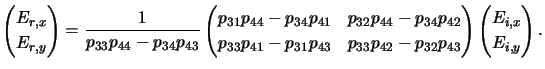 |
(C.25) |
The overall transfer matrix algorithm now consists of two
steps:
-
- 1.
- Firstly, the propagation matrix
 in (C.26) is
calculated and the reflected amplitudes are
derived from the incident ones by (C.29).
The lateral field
uair(0) occurring at the
up-most interface between air and stack is thus determined.
in (C.26) is
calculated and the reflected amplitudes are
derived from the incident ones by (C.29).
The lateral field
uair(0) occurring at the
up-most interface between air and stack is thus determined.
- 2.
- Secondly, the recursion formula (C.24) is evaluated at
any desired vertical position z. From the lateral
field components
u(z) the vertical ones can readily
be calculated from (C.4) and the overall EM field is
obtained.
Next: D. Nonplanar Material Interface
Up: C. Stratified Medium
Previous: Propagation Matrix
Heinrich Kirchauer, Institute for Microelectronics, TU Vienna
1998-04-17