Next: 7. Organic Semiconductor Device
Up: 6. Space Charge Limited
Previous: 6.2 Theory
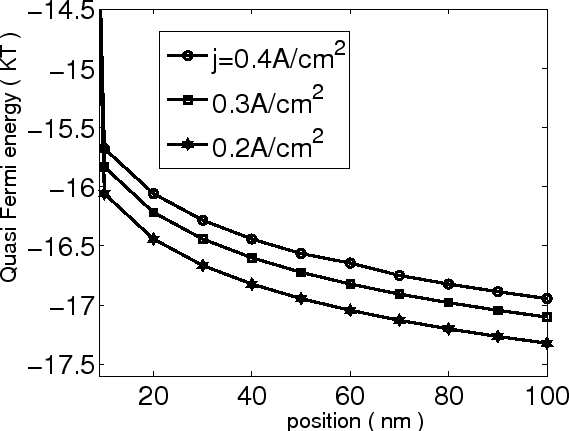
First we solve (6.8) numerically. The position dependence of the quasi Fermi
energy is shown in Fig 6.2. The parameters are
 cm
cm ,
,  A/cm
A/cm ,
,  cm/Vs,
 ,
,
 and the sample thickness
  nm. It can be seen that the
quasi Fermi-energy decreases with position and increases with current density. Near
the contact, the quasi Fermi energy decreases very quickly.
nm. It can be seen that the
quasi Fermi-energy decreases with position and increases with current density. Near
the contact, the quasi Fermi energy decreases very quickly.
Figure 6.2:
Spatial distribution of the quasi Fermi energy for different current
densities.
|
|
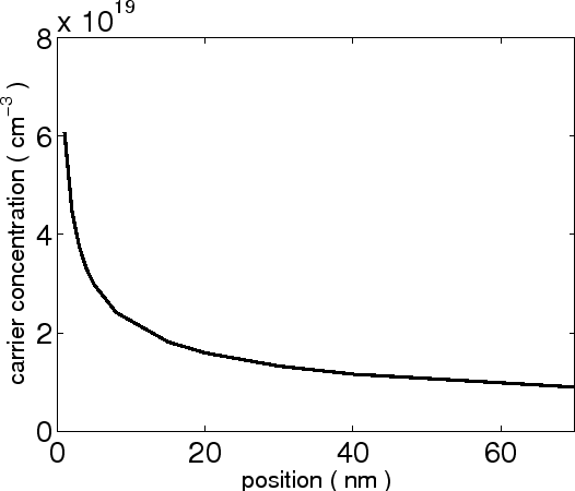
Figure 6.3:
Spatial distribution of the carrier concentration near the contact for A/cm.
|
|
We treat the metal electrode as site 0 with Fermi energy as  , where
  is
the metal work function. The Ohmic contact at
is
the metal work function. The Ohmic contact at  implies that the
field must drop to zero at this coordinate, so that
implies that the
field must drop to zero at this coordinate, so that
 .
.
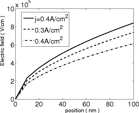
Figure 6.4:
Spatial distribution of the electric field at different current
densities.
|
|
Fig 6.3 shows that the carrier concentration decreases from the contact. Fig 6.4 shows
the field distribution in OLED with the same
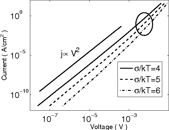
parameters as in Fig 6.2. The  characteristics are plotted in Fig 6.5 for different
 ,
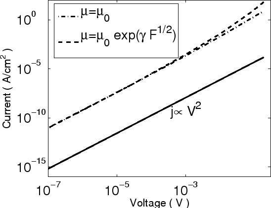
where the parameters are the same as Fig 6.2. As we can see, at low voltages
and current densities, the current
follows a
,
where the parameters are the same as Fig 6.2. As we can see, at low voltages
and current densities, the current
follows a
 characteristics, which may suggest either the
trap-free case or the shallow-trap case. At higher voltages, the space charge
is formed mainly by carriers occupying states above Fermi energy and the
current increases with voltage faster than
characteristics, which may suggest either the
trap-free case or the shallow-trap case. At higher voltages, the space charge
is formed mainly by carriers occupying states above Fermi energy and the
current increases with voltage faster than  . This behavior is also
predicted by a SCLC model based on an exponential DOS distribution [124], where
. This behavior is also
predicted by a SCLC model based on an exponential DOS distribution [124], where
The parameter
 varies between about 1 and 4,
  is the characteristic
energy of the exponential DOS and
is the characteristic
energy of the exponential DOS and  is the layer thickness of LED.
Figure 6.5:
Current-voltage characteristics of a sample with Gaussian DOS
distribution parametric in temperature.
|
|
Figure 6.6:
The effect of the field dependent mobility on the space charge
limited current.
|
|
The available models for SCLC transport assume constant mobility, and include
or neglect traps. However, it was found that the mobility in organic semiconductors
depends on the local electric field [119].
Integrating (6.5) yields
 |
(6.8) |
(6.6) is rewritten as
 |
(6.9) |
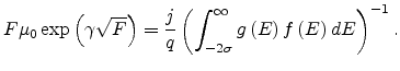
Substituting (6.9) into (6.8), we can obtain a new equation for quasi Fermi-energy as
The quasi Fermi energy and electric field distribution can be obtained by solving
(6.10) numerically. Fig 6.6 illustrates the effect of electric field dependent mobility on SCLC with
 (m/V)
(m/V) and
and  cm/Vs. Other parameters are the same as
in Fig 6.3. For comparison, SCLC with constant mobility and the standard SCLC model
are also plotted as well. It should be observed that our model departs
slightly from the standard one at high current densities.
cm/Vs. Other parameters are the same as
in Fig 6.3. For comparison, SCLC with constant mobility and the standard SCLC model
are also plotted as well. It should be observed that our model departs
slightly from the standard one at high current densities.
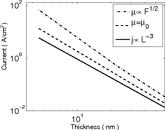
Figure 6.7:
The relation between organic layer thickness and space charge limited
current.
|
|
For light emitting diodes, it is important to distinguish if the device is
controlled by injection at the contact or by currents in the bulk of the organic
layer. To determine the dominant mechanism, an understanding of the thickness
scaling is required [128,129]. The thickness dependent SCLC in
Child's law model is given as [122]
 |
(6.10) |
The relation between layer thickness and SCLC in our
model is shown in Fig 6.7 assuming the same parameters as in Fig 6.2. The
thickness dependence of the current is also of the
form
 with
with  for the constant mobility case and
  for
the field dependent mobility case. In both cases
for
the field dependent mobility case. In both cases  is slightly bigger than
  as in the standard model.
Next: 7. Organic Semiconductor Device
Up: 6. Space Charge Limited
Previous: 6.2 Theory
Ling Li: Charge Transport in Organic Semiconductor Materials and Devices