6.1 Decomposition Identification
Geometry decompositions and templated meshes and geometries have been introduced in Chapter 4. This section deals with the identification processes of geometry decomposition and how they are related to templated structures.
Let
 be an
be an  -dimensional multi-region geometry and
 a decomposition of
 .
The geometry decomposition
.
The geometry decomposition  can be represented with a templated geometry, if the interior of every element of
  has just one region. The interior is required, because points on block interfaces are allowed to be in multiple regions. If the requirement is fulfilled, a templated geometry
  is said to be related to the decomposition
  , if the structure instance of
  is equal to
 and for every decomposition element of
  , there is an instance in
  , which is equal to the decomposition element.
Any given geometry can be represented using a templated structure.
For example, for every multi-region geometry, a trivial templated structure can be defined, which has one template for every region (being the region). Every template has only one instance indicated by the identity transformation function and the region indicator of the corresponding region.
However, there is no benefit in using templated structures with this trivial approach.
Except for very simple meshes, the memory consumption of a transformation function is far less than for a mesh.
Therefore, it is advantageous to have a high number of instances per mesh template.
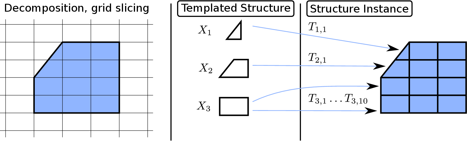
Figure 6.1 visualizes the benefit of using multiple transformation functions with just one small template in contrast to the trivial decomposition.
Figure 6.2:
Boundary dependencies in a templated geometry
|
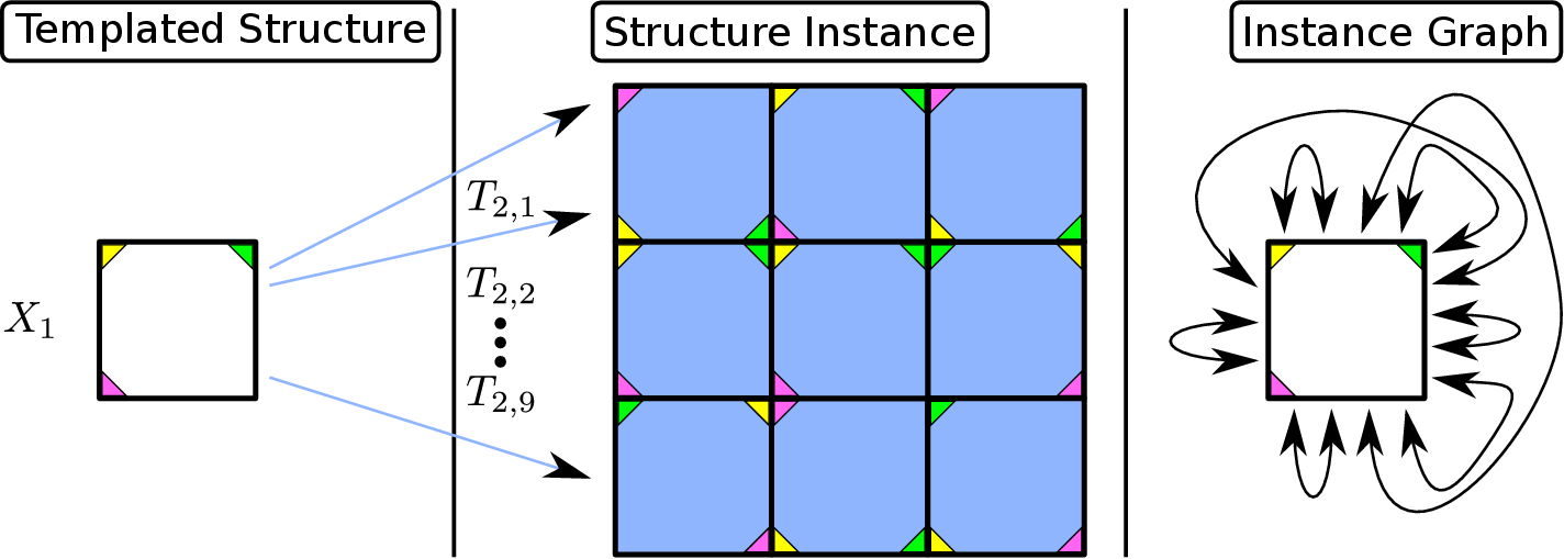
The green, yellow, and purple triangles are included in the drawing to indicate the orientation of the instances. Although there is only one template, all  instance interfaces of two pairwise different instances have different configurations, i.e., there are no two instances, the instance interface of which includes the same boundary parts. Therefore, there are many dependencies of the boundary elements of a corresponding mesh template for instance interfaces of two pairwise different instances have different configurations, i.e., there are no two instances, the instance interface of which includes the same boundary parts. Therefore, there are many dependencies of the boundary elements of a corresponding mesh template for  as indicated by the instance graph on the right. as indicated by the instance graph on the right. |
On the other hand, according to Lemma 4.2, each instance interface potentially introduces new constraints and dependencies for the boundary mesh of the corresponding template, as shown in Figure 6.2. These constraints restrict several operations in algorithms presented in Section 5.2, which potentially lowers the effect of quality improvement algorithms.
It is therefore important to find a balance between memory savings and template dependencies by choosing a decomposition which has many similar blocks but as few dependencies between block templates as possible.
In general, it is hard to find the optimal decomposition of a mesh or geometry, if there even is any. Some methods for finding a decomposition of meshes and/or geometries are presented in this section. All except graph-based decomposition methods work for geometries.
Trivial decomposition simply decomposes a geometry or mesh into only one decomposition element for each region, being the geometry or mesh region. The resulting templated structure has one template for every region, each with just one instance using the identity transformation function and the corresponding region indicator.
Grid slicing is a method, where a (regular) grid is laid over a geometry. The geometry is then sliced according to the overlay grid to obtain a decomposition of the geometry as visualized in Figure 6.3. Using a regular equidistant grid on a single-region geometry potentially results in many similar blocks which can originate from a small number of templates. However, due to the similarity to quad/octtree-based mesh generation algorithms, this method potentially creates blocks with bad shapes near the boundary of the geometry (cf. Figure 3.3).
Graph-based decompositions are methods based on graph partitioning algorithms [22]. Given a mesh or a multi-region mesh, the dual mesh or corresponding graph is generated by using each cell as a node. Two cells are connected, if they share a facet.
Using a graph partitioning algorithm, the mesh can be decomposed according to the resulting graph partition. This method only works well for meshes but not for geometries. Additionally, it is very unlikely that the mesh decomposition created by this method results in mesh parts which are similar to each other and therefore can share a common template.
If available, domain knowledge can be used for decomposition methods. For example, if a copy operation of a part-geometry has been performed in the CAD process, this information could be re-used for the geometry decomposition. This approach only works in special cases where this domain knowledge is available and accessible. Also, the decomposition algorithm has to be formulated separately for each type of domain knowledge making these types of decomposition methods impractical.
In the field of automatic quadrilateral and hexahedral mesh generation, a lot of algorithms heavily rely on block decomposition methods [100][102][107], which can also be used for geometry decomposition. Mesh decomposition based on these methods is beneficial for quadrilateral or hexahedral mesh generation, but they do not offer guarantees for finding similar blocks. However, in CAE applications, decompositions with similar blocks are likely.
There are also algorithms which automatically detect general similarities in objects [61][99].
However, many of these algorithms are computationally intensive. Additionally, they work with points sampling and therefore are not stable. Methods and algorithms for automatic similarity detection are covered in Section 3.3.2.
A very promising decomposition method relies on symmetries of the geometry.
A set
 is said to have a symmetry, if there is a non-trivial rigid function
  under which
  is invariant, i.e.,
  .
There are two types of symmetries, which are of primary interest, being reflective symmetries and rotational symmetries (methods and algorithms for automatic detection of these types of symmetries are presented in Section 3.3.1).
These two types of symmetries are covered in detail in Section 6.2 and Section 6.3. Combinations of these symmetries, like multiple point symmetries or a combination of reflective and rotational symmetry, are discussed in Section 6.4.
.
There are two types of symmetries, which are of primary interest, being reflective symmetries and rotational symmetries (methods and algorithms for automatic detection of these types of symmetries are presented in Section 3.3.1).
These two types of symmetries are covered in detail in Section 6.2 and Section 6.3. Combinations of these symmetries, like multiple point symmetries or a combination of reflective and rotational symmetry, are discussed in Section 6.4.
florian
2016-11-21
![\begin{subfigure}
% latex2html id marker 11988
[b]{0.90\textwidth}
\centering
...
...mplated_mesh_memory_benefit_1}
\caption{Trivial decomposition}
\end{subfigure}](img1007.gif)
![\begin{subfigure}
% latex2html id marker 11994
[t]{0.90\textwidth}
\centering
...
...igures/templated_mesh_memory_benefit_2}
\caption{Grid slicing}
\end{subfigure}](img1008.gif)