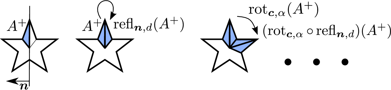
6.4.2 Combination of Reflective Symmetry and Rotational Symmetry

The approaches introduced in Section 6.2 and Section 6.3 can be combined for sets which have a rotational symmetry and a reflective symmetry. This type of combination requires the axis of rotational symmetry to be included in the reflecting hyperplane for 3D sets. This requirement is not needed for 2D sets, because the reflective hyperplane always passes through the rotation center.

Figure 6.15: Combination of reflective and rotational symmetries
Image combination_rotation_reflection_reconstruction

The set $ A$ has a rotational symmetry of order five and a reflective symmetry indicated by the hyperplane with the normal vector $ \bm{n}$. The subset for the reconstruction process is obtained by using one half of a slice which also has a reflective symmetry. The resulting subset $ A^+$ is then reflected around the reflecting hyperplane and in turn $ A^+$ and $ \operatorname{refl}_{\bm{n},d}(A^+)$ are rotated as described in Section 6.3.

Let $ A \subseteq {\mathbb{R}}^3$ be a set with a reflective symmetry depicted by $ \mathbb{H}_{\bm{n},d}$ and a rotational symmetry of order $ k$ with rotation center $ \bm{c}$ and rotation axis $ \bm{v}$, where the rotation axis is a subset of the reflecting hyperplane. Then, $ A$ has a total of $ k$ reflective symmetries, each defined by rotating $ \mathbb{H}_{\bm{n},d}$ around the axis of rotational symmetry by an angle of $ i\frac{360\degree}{k}, i = 0, \dots, k$. Additionally, there always exists a rotational symmetry slice which also has a reflective symmetry. Due to that reflective symmetry, this slice can be cut in half and used as a geometry template together with the transformation functions being the compositions of the reflection and all rotation transformation as visualized in Figure 6.15. The resulting templated structure is a templated geometry with the same property as the templated structure for reflective symmetries: The instance interfaces will always be conforming. Therefore, no boundary patch partition is needed during the mesh generation process and the templated mesh can easily be generated by creating any valid mesh.

The mesh generation process of a combined reflective-rotationally symmetric multi-region mesh is presented in Algorithm 6.5. Instead of using a normal slice as presented in Section 6.3, a half-slice is calculated using the reflecting hyperplane and the reflecting hyperplane rotated around the axis of rotational symmetry by an angle of $ \alpha/2$ (Lines 4-5). A multi-region mesh is generated for this half-slice using an arbitrary volumetric mesh generation algorithm with multi-region support (Line 7). The transformation functions for the templated mesh are obtained by composing the identity and the symmetry reflection with all rotation angles around the axis of rotational symmetry (Line 8). The final templated mesh is generated by using the regions of the generated mesh $ {({\mathcal{M}}, {\xi})}^+$ as mesh templates, each together with all transformation functions $ T$ (Line 9).

The theoretical improvement in memory and runtime is a factor of $ 2n$ for objects with a reflective symmetry as well as a rotational symmetry of order $ n$. Because the boundary patch partition is not required, Algorithm 6.5 has much less overhead compared to the mesh generation process described in Section 6.3. Therefore, performance increases are expected and evaluated in Chapter 7.


\begin{algorithm}
% latex2html id marker 12690
{\textbf{Algorithm} $\operatornam...
...tion for geometries with reflective and rotational symmetries
}
\end{algorithm}

florian 2016-11-21