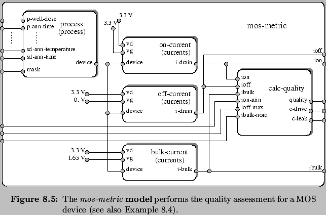
Having all parts of Figure 8.1 we need to create a network-model to establish the relations between these components. Figure 8.5 (Example 8.4) depicts the mos-metric model capable to evaluate the quality metrics for either a PMOS or an NMOS device, depending on the mask set which is supplied at the port mask.
The mos-metric model makes use of the process model and connects all of its input ports to the ``outside'' (by defining an empty list of private ports in the submodel description) in order to make them accessible to the optimization tool. Furthermore, three instances of the currents model are used under the names on-current, off-current, and bulk-current. Each of the latter uses a different combination of private settings at the vg and vd port. As a result, we obtain the drive current, the leakage current, and the substrate current at their output port i-drain. These values are finally used by the calc-quality model in order to compute the quality metric, the drive current constraint c-drive, and the leakage current constraint c-leak. The bulk-current model uses a gate potential of Vg=Vd,max/2 since the maximum of the substrate current occurs at this operating point [43]. Note that the outputs at the port i-drain of the models on-current, off-current, and bulk-current are made visible to the ``outside'' at the output ports ion, ioff, and ibulk, respectively.
Although we want to restrict our example to one device category, we briefly sketch a model which takes NMOS as well as PMOS devices into account. The cmos-metric model (Figure 8.6, Example 8.5) illustrates how the mos-metric model can be utilized to evaluate the quality metrics of an NMOS and a PMOS device simultaneously. It uses two mos-metric models under the names p-mos-metric and n-mos-metric and assigns them different mask sets at their input port mask. The cmos-metric model is especially necessary if parameters are varied by the optimization tool which have a strong influence on PMOS as well as NMOS devices, and, therefore, both categories need to be monitored during the optimization procedure.