

Next: 9.3.3 Deriving a Metric
Up: 9.3 Inverse Modeling of
Previous: 9.3.1 The Inverse Modeling
Although we could produce the electrical device by means of a full
process simulation, we are for simplicity using MAKEDEVICE [5]
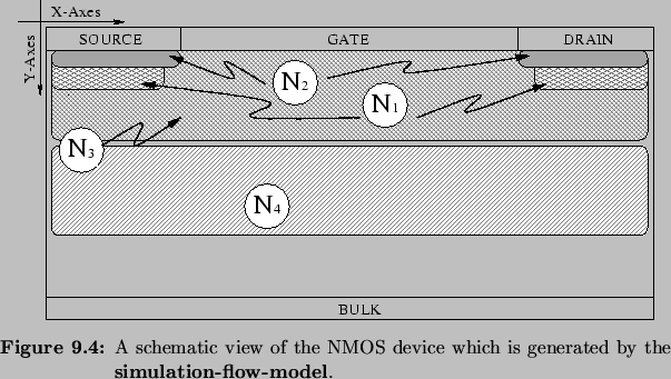
to create a synthetic NMOS device. Figure 9.4 shows
a schematic view of a semiconductor device produced with MAKEDEVICE. It
contains several elements which build up the doping profile. They are
either profiles of Gaussian, Pearson, or constant shape. There are
doping elements for the source and drain regions, for the lightly
doped drain, for the threshold implant, and for the punch trough
implant.

MAKEDEVICE allows the user to control these doping elements by means of
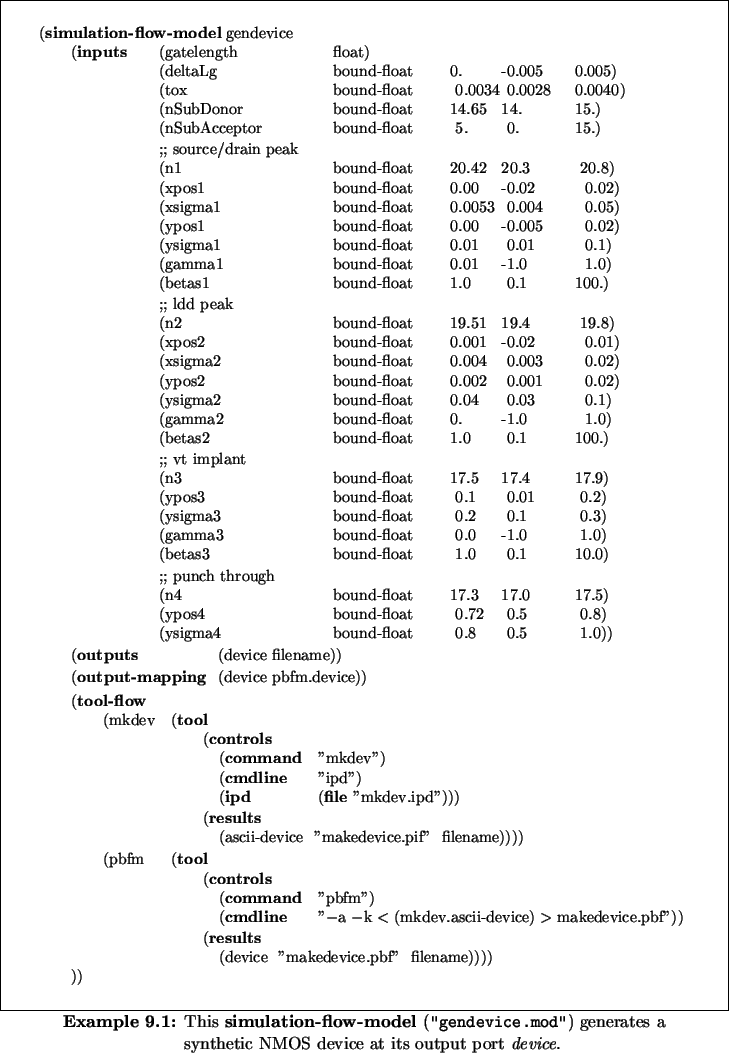
parameters of its input deck. Example 9.1 shows a
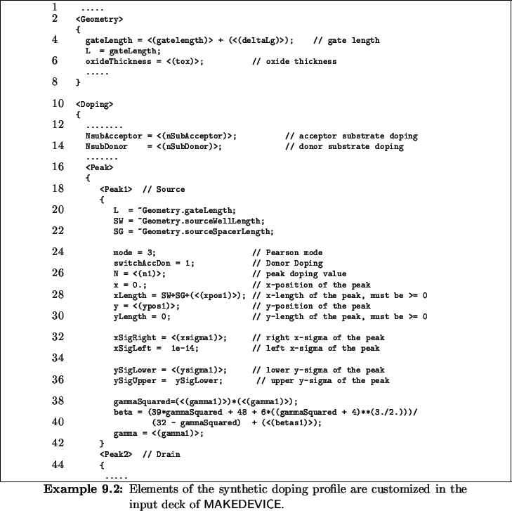
simulation-flow-model which encapsulates MAKEDEVICE. Example 9.2
lists the input deck which is used to describe the doping profiles of
the NMOS device. This input deck contains template symbols which refer
to ports of the simulation-flow-model. Thus, one is able to specify the
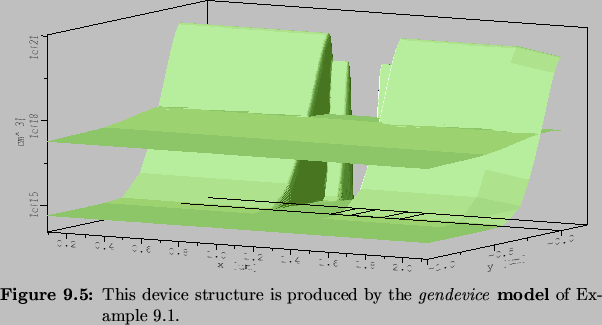
parameters of the doping profile at the model's ports. A sample
device produced by this model is depicted in
Figure 9.5.


Next: 9.3.3 Deriving a Metric
Up: 9.3 Inverse Modeling of
Previous: 9.3.1 The Inverse Modeling
Rudi Strasser
1999-05-27

