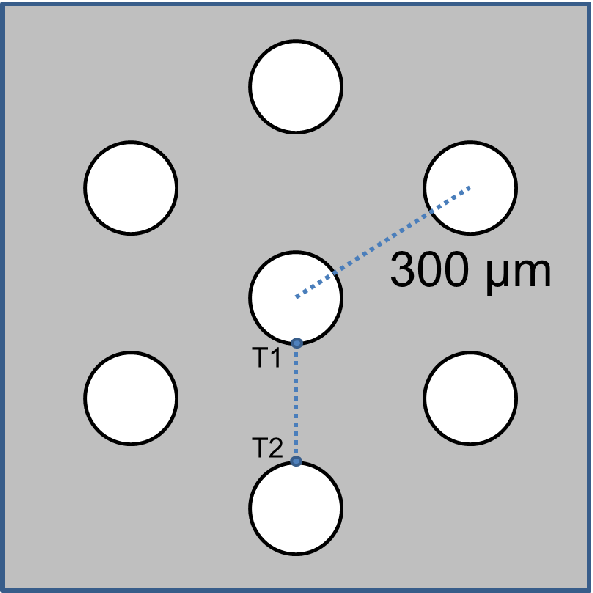
| Figure 4.9.: | A particular arrangement of 7 TSVs. The vias are equidistant (300 m)
from each other. m)
from each other. |
Although one isolated TSV is not very common in real devices, its analysis is extremely useful. The vias are usually arranged following a particular pattern, which causes an interaction between the stress fields around the TSVs. As an example consider an arrangement of TSVs as shown in Fig. 4.9. It is irrelevant if the via is filled or unfilled, since the stress around the TSV in both cases follows the same decaying law (proportional to the inverse of the distance), as was derived in (4.9) and is shown in Lu’s solution [82].
2D simulations of the 7 TSVs were performed. The result enables the analysis of the stress field interaction between the TSVs as depicted in the von Mises plot of Fig. 4.10. One can note a peculiar pattern formed. Superposition of the individual stress fields of the TSVs leads to stress free regions in between them. Fig. 4.11 details the stress between the two TSVs along the line T1-T2 from Fig. 4.9 and it shows the superposition of the stress field of the two vias as described by (4.9).
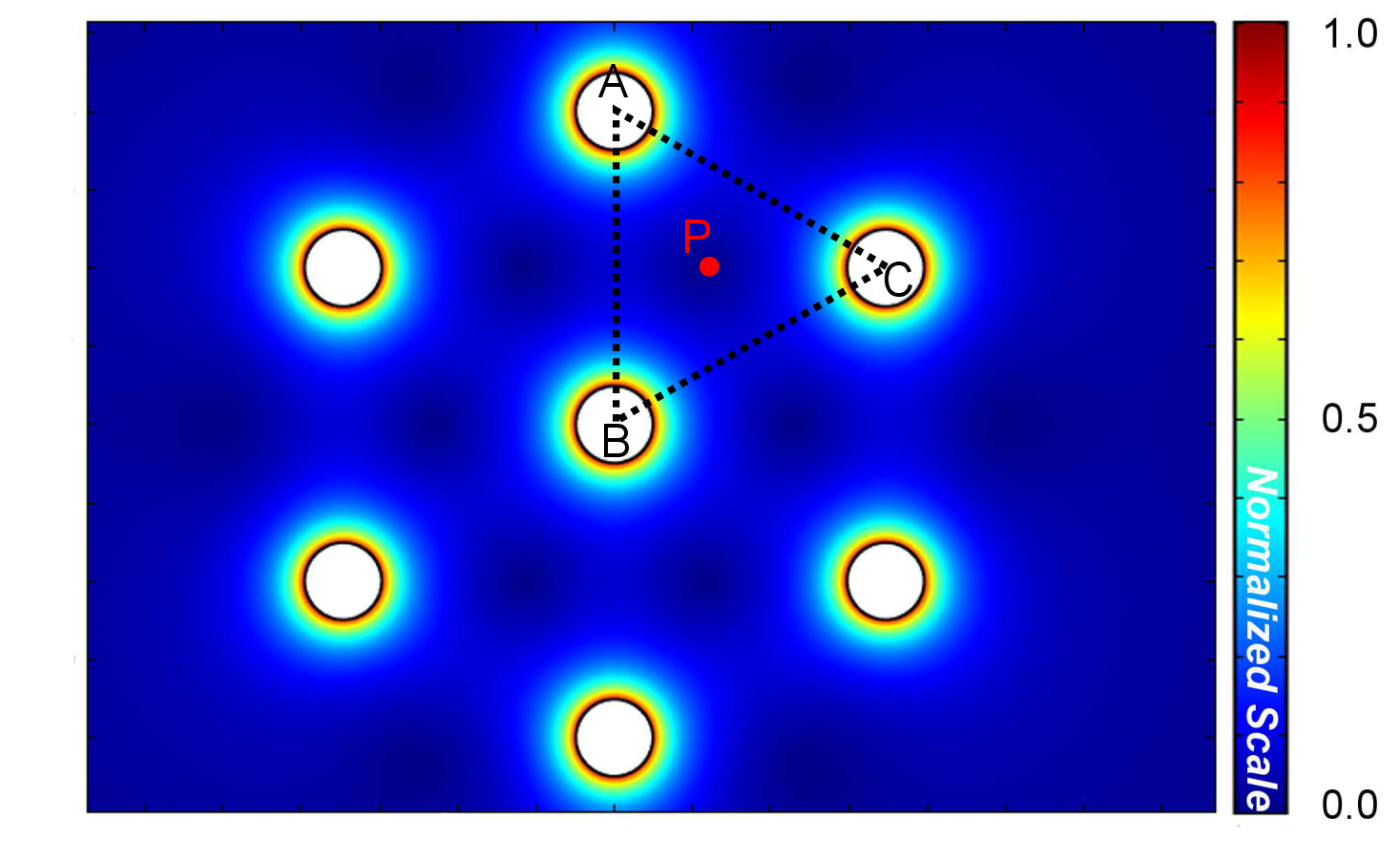
| Figure 4.10.: | Von Mises stress of the 7 TSVs pattern. The stress superposition between the TSVs creates stress-free spots. The TSVs’ placement can be chosen to minimize the stress impact in silicon. |
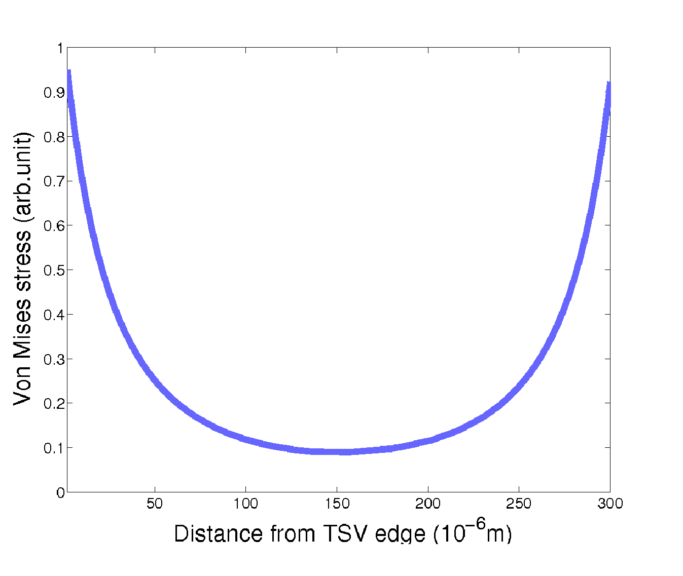
| Figure 4.11.: | Von Mises stress between two TSVs. The characteristic stress curve of each TSV is superimposed to its neighbor, creating this particular pattern. |
Actually, it is possible to use the stress solution for one TSV and the superposition principle to determine the localization of the stress-free zones. Consider the triangle ABC of Fig. 4.10, where the stress inside this triangle is determined only by the TSVs at each of its vertices. The influence of the other TSVs in the arrangement is negligible because of the large distance to the triangle zone. Therefore the localization of the stress minimum value is given by the solution of the problem posed by
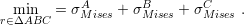 | (4.11) |
The superscripts A, B, and C refer to the TSVs on the triangle vertices of Fig. 4.10. In this
situation,  and
and  of each TSV is given by (4.9) and (4.10) translated according to
the origin of the coordinate system used for the minimization problem in the triangle. The
point obtained for this particular arrangement is indicated in Fig. 4.10. It is located 85
of each TSV is given by (4.9) and (4.10) translated according to
the origin of the coordinate system used for the minimization problem in the triangle. The
point obtained for this particular arrangement is indicated in Fig. 4.10. It is located 85 m
in the x-direction and 150
m
in the x-direction and 150 m in the y-direction away from the center of the TSV centered
in Vertex B.
m in the y-direction away from the center of the TSV centered
in Vertex B.
In fact, this point is the geometric center of the triangle ABC, which in an equilateral triangle is equally far from each vertex. Therefore, it is the point inside the triangle least influenced by the stress field of the three TSVs. This means that it is possible to determine the localization of each minimum in this arrangement of TSVs just by determining the geometric center of each triangle. For any other arrangement a new minimization problem must be formulated as was done in (4.11).
The TSVs arrangement can be used to control the stress around the vias. It can be applied to maximize the area available for devices as well as to increase the mechanical stability of the entire structure. The solution (4.8) is, in principle, only valid to calculate the stress around the middle of the via, however it can also be used as an estimate of the stress in the top and bottom of the TSV structure, as depicted in Fig. 4.12. Therefore, the procedure described here can be easily applied to the placement of TSVs, with the advantage that the development of the analytic solution gives speed and simplicity to the process.
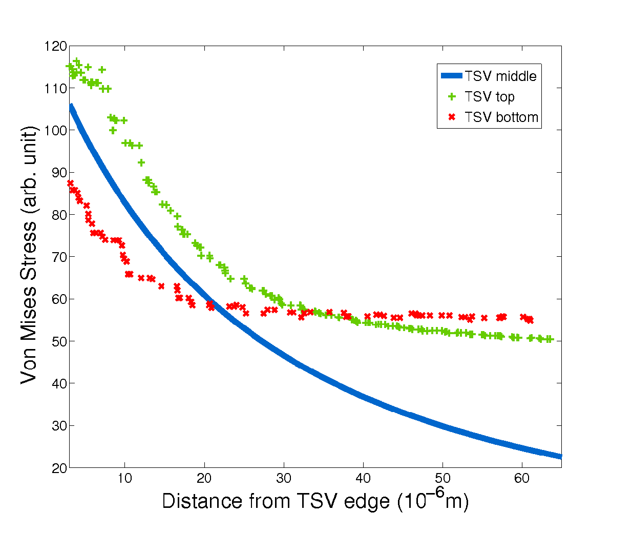
| Figure 4.12.: | Comparison between the stress along the radial direction at the top and bottom of the TSV with the stress in the middle (analytical solution). For points close to the TSV edges, the analytical solution provides a fair approximation. For points further from the TSV edge (20um), it can still be used as a lower bound estimate for the stress. |