|
|
|
|
||
| Previous: 3.8.1 The Empirical Pseudopotential Method Up: 3.8 EPM for Arbitrary Strain Next: 4. Quantum Confinement | ||||
To handle general strain conditions, four modifications in the band structure calculation have to be taken into account:
(i) The direct lattice vectors
![]() of the strained crystal are
calculated by deforming the vectors
of the strained crystal are
calculated by deforming the vectors
![]() of the unstrained crystal
according to (3.30). From the strained lattice basis vectors,
the strained reciprocal lattice vectors
of the unstrained crystal
according to (3.30). From the strained lattice basis vectors,
the strained reciprocal lattice vectors
![]() can be obtained. These
are used to calculate the strained lattice vectors of the reciprocal lattice
which are used in the expansion of the pseudo wave function
(3.102) and in the calculation of the normalizing volume of the
strained unit cell
can be obtained. These
are used to calculate the strained lattice vectors of the reciprocal lattice
which are used in the expansion of the pseudo wave function
(3.102) and in the calculation of the normalizing volume of the
strained unit cell ![]() as given in (3.31).
as given in (3.31).
(ii) Since the local pseudopotential form factors enter the calculation at the
strained reciprocal lattice vectors, an interpolation of the pseudopotential is
required (see Figure 3.14). Different expressions have been proposed
in [Friedel89,Rieger93]. In this work, the pseudopotential form factors of
the strained lattice are obtained by performing a cubic spline interpolation
through the pseudopotential form factors, ![]() ,
, ![]() ,
, ![]() ,
, ![]() , and
, and
![]() . Following [Rieger93],
. Following [Rieger93], ![]() is set to
is set to
![]() , and
, and
![]() , where
, where
![]() denotes the
Fermi wave vector of the free electron gas.
denotes the
Fermi wave vector of the free electron gas.
|
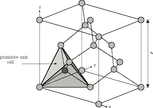
(iii) In Figure 3.15 a schematic plot of the diamond structure with
the primitive unit cell is plotted. The latter has a tetragonal shape. The
vertex atoms of the tetrahedron and the central atom located at
![]() belong to a different
fcc-lattice. While the position of the vertex atoms of the tetrahedron
(indicated in light-grey) can be calculated from macroscopic strain, the
absolute position of the central atom in the bulk primitive unit cell (dark
grey) remains undetermined. To obtain the exact position of the central atom an
additional parameter for the displacement has to be taken into account.
belong to a different
fcc-lattice. While the position of the vertex atoms of the tetrahedron
(indicated in light-grey) can be calculated from macroscopic strain, the
absolute position of the central atom in the bulk primitive unit cell (dark
grey) remains undetermined. To obtain the exact position of the central atom an
additional parameter for the displacement has to be taken into account.
![\includegraphics[scale=1.0, clip]{inkscape/intStrain4.eps}](img683.png) |
A schematic plot showing the change of atomic positions in the primitive unit cell under strain is given in Figure 3.16. In the unstrained lattice, the central atom is positioned at the center of the tetrahedron, which is indicated by a white circle in Figure 3.16a. Under strain the vertex atoms change their positions and the central atom is displaced from the center of the distorted tetrahedron (see Figure 3.16b). In order to minimize the nearest neighbor central force energy of the system, the central atom moves towards the center of the four vertex atoms. However, opposing this reduction of energy is the increase of nearest neighbor non-central force energy and far-neighbor energy [Kleinman62]. Thus, the central atom does not completely relax to the center of the strained tetrahedron as indicated in Figure 3.16c.
In the case of general strain, the additional displacement of the central atom
with respect to the four vertex atoms of the unit tetrahedron in the diamond
structure can be modeled in terms of an internal strain parameter (displacement
factor) ![]() : First, the positions of the vertex atoms and the central atom
are derived from the macroscopic strain. Then the center of the four vertex
atoms is determined. If the internal strain parameter
: First, the positions of the vertex atoms and the central atom
are derived from the macroscopic strain. Then the center of the four vertex
atoms is determined. If the internal strain parameter ![]() is set to zero, the
central atom retains its position determined from the macroscopic strain only;
if
is set to zero, the
central atom retains its position determined from the macroscopic strain only;
if ![]() the central atom moves to the center of the four vertex atoms, and
all four bonds are of the same length. As previously discussed, neither of the
two extrema occurs in a real crystal and a appropriate value
the central atom moves to the center of the four vertex atoms, and
all four bonds are of the same length. As previously discussed, neither of the
two extrema occurs in a real crystal and a appropriate value
![]() for the internal strain parameter has to be used.
for the internal strain parameter has to be used.
For the determination of the internal strain parameter of Si we performed
calculations with the ab-initio total-energy and molecular-dynamics program
VASP (Vienna ab-initio simulation program)
[Kresse93,Kresse94,Kresse96a,Kresse96b,Kresse99]. A value of ![]() was
extracted, which is very close to previous theoretical calculations of
Nielson [Nielsen85], who extracted a value of 0.53, and the experimental
result
was
extracted, which is very close to previous theoretical calculations of
Nielson [Nielsen85], who extracted a value of 0.53, and the experimental
result
![]() [Cousins87].
[Cousins87].
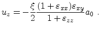
If stress is applied along a fourfold axis
![]() no internal
displacement occurs. In this case the center of the deformed primitive unit cell
coincides with the position of the central atom determined from macroscopic
strain and all four bonds are of the same length. For the stress directions
no internal
displacement occurs. In this case the center of the deformed primitive unit cell
coincides with the position of the central atom determined from macroscopic
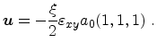
strain and all four bonds are of the same length. For the stress directions
![]() and
and
![]() analytical expressions for the
internal displacement can be derived:
analytical expressions for the
internal displacement can be derived:
 |
(3.110) |
 |
(3.111) |
(iv) Finally, strain-induced loss of symmetry gives rise to a change in shape
and volume of the irreducible wedge of the first BZ [Ungersboeck06a].
Irreducible wedges under various strain conditions were identified in
Section 3.5. Only if the proper wedge is identified, redundancy
in the band structure calculations can be avoided.
|
|
|
|
||
| Previous: 3.8.1 The Empirical Pseudopotential Method Up: 3.8 EPM for Arbitrary Strain Next: 4. Quantum Confinement | ||||