The solver module is responsible for calculating the solution vector of the inner linear equation system. Basically, it is a separate module, but is invoked by the assembly module. As discussed in the next chapter, the solver module provides three in-house solvers as well as an interface to external solver modules. To summarize the various steps between assembling the linear equation system and returning its complete solution vector to the simulator, a schematic overview is given in Figure 4.4.
In the upper left corner the Newton iteration control of the simulator is
represented, which uses an interface class to access the assembly. The inputs
of the assembly module are the contributions of the various segment and
boundary models implemented in the simulator, which are subsequently called.
Following the black solid lines beginning at the interface, the four matrices
![]() ,
,
![]() ,
,
![]() , and
, and
![]() are assembled by using the flexible sparse
storage class based on balanced binary trees.
are assembled by using the flexible sparse
storage class based on balanced binary trees.
These structures are then converted to the MCSR format and compiled resulting in the complete linear system, which is pre-eliminated to obtain the inner and outer system. The inner one is sorted, scaled, and finally passed to the solver module. After the solver module has returned the solution vector (or solution vectors in case of multiple right-hand-side vectors), the assembly module has to back-substitute the pre-eliminated equations as well as revert scaling, sorting, and the variable transformation to obtain the complete solution vector(s).
The Newton adjustment levels (red dashed lines) reuse already existing MCSR structures to reduce the assembling effort: the flexible sparse structures may be skipped completely, and during compilation and pre-elimination much simpler functions (red bold boxes) can be used than in the conventional mode (black bold boxes with slash). The latter requires symbolic phases in order to calculate the result storage requirements, which are known for the already existing structures. In the next section, the Newton adjustment is described in more detail.
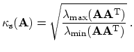
As the assembly module also provides an interface to a system for calculating eigenvalues, the system matrices shown in Figures 4.2 and 4.3 have been analyzed. The spectral condition for a non-symmetric matrix [52] is given by
 |
(4.26) |
A spectral condition in the order of ![]() and the precision of the numeric
representation of
and the precision of the numeric
representation of ![]() approximately results in an error of
approximately results in an error of ![]() [52]. Thus, a small error follows from a small residual only for a
small condition number [188]. As it is demonstrated by the results in
Table 4.1, the condition number is significantly improved by twelve orders
of magnitude due to the applied measures.
[52]. Thus, a small error follows from a small residual only for a
small condition number [188]. As it is demonstrated by the results in
Table 4.1, the condition number is significantly improved by twelve orders
of magnitude due to the applied measures.
![\includegraphics[width=0.98\linewidth ]{figures/schematic3ac.eps}](img785.png)