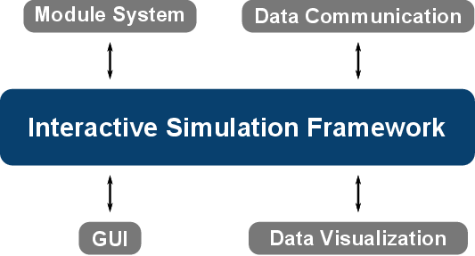
Figure 6.2: An interactive simulation framework consists of four essential parts, those
being a module system, a data communication layer, a GUI, and a data visualization
facility.
Considering a typical simulation workflow, such as performing a device simulation of a transistor device, generates concrete requirements regarding an interactive simulation platform. In a first step the simulation domain representing the electronic device must be discretized - yielding a mesh - and visualized to the end user in a simplified form. The visualization of the simulation domain aids the end user to setup the simulation, by providing a visual target for the simulation setup. Device regions are not abstracted by numbers or names but actually rendered on the screen, allowing to assign segment roles in a natural manner. Therefore, it is not required to visualize the mesh elements by default but rather the so-called surface representation, enabling end users to grasp the shape and size of the simulation domain. However, advanced users with an additional background in mesh generation can choose to inspect the mesh visually supported by computational aids, e.g., algorithms which identify badly shaped mesh elements, especially required for three-dimensional meshes.
Based on the discretization, device-specific meta information such as material data and doping information has to be assigned to the mesh, elevating the mesh to a device. As already discussed in Section 4.2.1, the doping information is either based on the result of a numerical process simulation or according to an analytic approach where the latter is of particular importance for day-to-day use as no time-consuming numerical simulation is required. The thus generated device acts as an input for the actual device simulation step, where the physical problem is defined by appropriate models, such as transport and scattering models, and boundary conditions. The simulation is conducted and the results are visualized allowing the end user to analyze the device properties. To this end, not only three-dimensional quantity rendering is required, allowing to show, for instance, electron concentration distributions on top of a mesh, but also charts are required to visualize, for example, current-voltage characteristics.
Based on these requirements, the essential key aspects of an interactive simulation framework are extracted (Figure 6.2), those being a module system, a data communication layer, a GUI, and a data visualization facility. A module system enables to separate different functionalities in standalone entities - thus enabling reusability - whereas a data communication mechanism allows the modules to exchange data, such as a device. A visualization facility enables to render meshes and quantities, such as simulation results, therefore enabling the end user to visually perceive the data, thus significantly aiding the end user in the various evaluation steps. A GUI provides a general high-usability platform to the end user, enabling to conveniently interact with the simulation platform. Note that the visualization mechanism is embedded into the GUI. However, as the visualization mechanism has rather specialized requirements, such as rendering data fields on top of meshes, as compared to general interaction elements of a GUI, like buttons and dialogs, they are considered separately.
Where the requirements and challenges of the module system and the data communication are similar to the already discussed approaches in Section 5.2, schedulers are typically not required with an interactive simulation framework. Instead of executing a set of modules in a single execution run - which indeed would require scheduling - only one module is usually executed at the end user’s behest. This peculiarity stems from the primary area of application as a platform for providing individual simulation tools. Consequently, the results of each simulation are likely to be investigated by the end user, thus a single-module execution mode merits special consideration.
Contrary to the previously discussed component execution framework (Chapter 5), a key aspect of an interactive simulation framework is the ability to interact with the end user, represented by a GUI and a data visualization mechanism, such as three-dimensional rendering. Therefore, the GUI takes the place of the configuration mechanism as introduced in the context of a component execution framework. Each of these four introduced key aspects is discussed in detail in the following.