Next: 4.2 Optimization Strategies Up: 4.1 Basic Issues on Previous: 4.1.1 Optimization Loop Contents
Up to a certain level, a graphical user interface (GUI) can provide such features. Another fact that has to be considered is that some of the assumed (commonly used) settings made by the GUI may not be always wanted by experienced users. These well experienced users often prefer a text-based input deck to specify their real needs. For that particular use case, the GUI does not help the user very much. Therefore, in the concept phase of the GUI, the decision has been made in favor for well trained technicians and experts and for people which are not so experienced. Hence, the concept covers both categories of users.
However, an important feature requested from many design engineers is to have a pool of ready-to-start templates which offer a very expedient introduction into the optimization methods as well as a rapid initial setup of their optimization tasks, even for very complicated configurations. Gradually, the original templates are often adapted in order to meet more specific and more complex demands. The big benefit in that use case is to have a very fast set-up of the optimization run and a very steep learning characteristics of the design engineers with only a few minutes for the introductory and the set-up task.
Thus, the design decision at the Institute for Microlelectronics has been made in favor for experts with a large pool of such templates and example files. Since most of the simulators have to be adjusted by experts for the appropriate technology and IT equipment, additional installation of templates and examples would not be too time consuming and is therefore not an issue. With these features and a plenty of templates and examples files, the software is able to provide sufficient information and configuration possibilities for experts as well as ready-to-start templates for propaedeutic examples to show and teach the major features. Most of the time, even experts use for simulation and optimization mainly well established templates which have been once created or adapted for a certain class of problems.
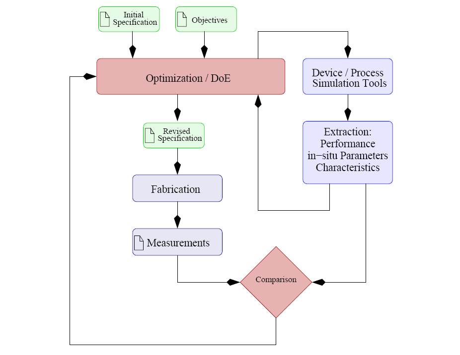
As depicted in Figure 4.2 the optimization loop can be involved at several levels of the design process. [234,235]. The first and fastest optimization loop is the one depicted on the left hand side of Figure 4.2. It shows the optimization with respect to the parameters of the models used in the process and device simulations. At the end of this optimization loop, the simulation results are compared with the reference data which can be certain figure of merits like guidelines or constraints or can be data obtained from measurements of real devices. The second optimization loop considers the fabrication process as well, where the process specification and the fabrication receipts are changed as the optimization procedure suggests by providing intermediate optimization results. However, design engineers have to verify the intermediate optimization results as well as final results because the obtained data set are numerical the best, but might be physically not reasonable, if for instance certain constraints cannot handle or determine the capabilities of the fabrication processes.