Previous: 2.2.2 Lateral IGBTs Up: 2.2 Lateral High-Voltage Devices for Smart Power Applications Next: 2.2.4 Double Gate Lateral Inversion Layer Emitter Transistor
In order to reduce the on-resistance of HVICs, LIGBTs which utilize bipolar mode conduction (conductivity modulation at the drain region), have been proposed. However, the level of conductivity modulation of LIGBTs is limited due to the latch-up capability of the cathode region. Further improvement in the on-state voltage drop can be realized by using the devices which have a thyristor mode operation together with a MOS gate. Therefore, lateral MOS-controlled thyristors (LMCTs) have been suggested to provide improved latch-up susceptibility and the desired current saturation characteristic.
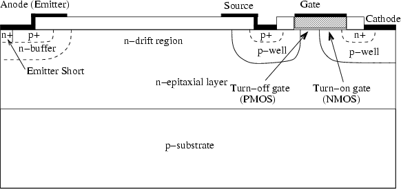
Figure 2.14 shows the cross section of the LMCT structure.
The LMCT has a four-layer ![]() -structure, with a cathode connected
to ground. The turn-on and turn-off gates are under the same gate
electrode. The turn-on gate is an NMOS device, formed by double diffusion
of the
-structure, with a cathode connected
to ground. The turn-on and turn-off gates are under the same gate
electrode. The turn-on gate is an NMOS device, formed by double diffusion
of the ![]() -well and the
-well and the ![]() -region of the cathode.
The turn-off device is a PMOS structure,
formed between the
-region of the cathode.
The turn-off device is a PMOS structure,
formed between the ![]() -well of the cathode and the
-well of the cathode and the ![]() -well of the source.
The channel created is determined by the bias voltage on the gate
electrode. In the forward blocking or off-state, for a cathode
voltage of 0V, the gate voltage must be less than the threshold voltage
of the turn-off PMOS device. Positive anode voltages are then blocked by the
source
-well of the source.
The channel created is determined by the bias voltage on the gate
electrode. In the forward blocking or off-state, for a cathode
voltage of 0V, the gate voltage must be less than the threshold voltage
of the turn-off PMOS device. Positive anode voltages are then blocked by the
source ![]() -well and the
-well and the ![]() -drift junction.
Leakage currents are limited to junction generated currents up to the
the avalanche point. In the on-state a positive voltage larger
than the threshold voltage of the
-drift junction.
Leakage currents are limited to junction generated currents up to the
the avalanche point. In the on-state a positive voltage larger
than the threshold voltage of the ![]() -diode (anode/
-diode (anode/![]() -buffer junction,
about 0.7V) is applied to the
-buffer junction,
about 0.7V) is applied to the ![]() -anode with respect to cathode, and the gate
to cathode voltage is increased to be larger than the threshold
voltage of the turn-on NMOS device. An
-anode with respect to cathode, and the gate
to cathode voltage is increased to be larger than the threshold
voltage of the turn-on NMOS device. An ![]() -channel is created and an electron
current flows from the cathode towards the drift region, which provides
the base current for the
-channel is created and an electron
current flows from the cathode towards the drift region, which provides
the base current for the ![]() -transistor.
-transistor.
Then positive feedback operation occurs if the sum of the common-base current
gains of the ![]() -transistor and the
-transistor and the ![]() -transistor exceeds one,
which turns the thyristor on.
The
-transistor exceeds one,
which turns the thyristor on.
The ![]() -source forms a
-source forms a ![]() -channel MOSFET with the base of the
-channel MOSFET with the base of the ![]() -transistor.
A
-transistor.
A ![]() -well is added at the source in addition to the
-well is added at the source in addition to the ![]() -contact to prevent
premature breakdown at the source because of its small junction curvature.
-contact to prevent
premature breakdown at the source because of its small junction curvature.
To turn the LMCT off, the holding current of the thyristor must be increased.
It is normally controlled by changing the ![]() -base resistivity
and the emitter short (anode short) area at the anode side.
With a small anode short area a lower forward drop and a lower holding current
can be expected, but it limits the turn-off capability.
The turn-off capability of LMCTs is evaluated by the maximum
controllable current which is the maximum current in the on-state above
which the device cannot be turned off. The current density that can be
turned off depends on the density (distributed PMOS area on the chip)
and effective resistance of the
turn-off PMOS structure. This turn-off time mainly depends on the
carrier recombination lifetime in the lightly doped
-base resistivity
and the emitter short (anode short) area at the anode side.
With a small anode short area a lower forward drop and a lower holding current
can be expected, but it limits the turn-off capability.
The turn-off capability of LMCTs is evaluated by the maximum
controllable current which is the maximum current in the on-state above
which the device cannot be turned off. The current density that can be
turned off depends on the density (distributed PMOS area on the chip)
and effective resistance of the
turn-off PMOS structure. This turn-off time mainly depends on the
carrier recombination lifetime in the lightly doped ![]() -drift region
and the drift length. However, the turn-on speed depends on the initial turn-on
area of the thyristor like in conventional thyristors and is
related to the density (distributed NMOS area on the chip) of the turn-on NMOS structure.
-drift region
and the drift length. However, the turn-on speed depends on the initial turn-on
area of the thyristor like in conventional thyristors and is
related to the density (distributed NMOS area on the chip) of the turn-on NMOS structure.
Turn-off of LMCTs is achieved by shorting the emitter junction
to get the ![]() -structure out of saturation. When a negative voltage is applied
to the gate relative to the cathode, the
-structure out of saturation. When a negative voltage is applied
to the gate relative to the cathode, the ![]() -channel first disappears,
and a
-channel first disappears,
and a ![]() -channel is formed at the turn-off PMOS structure.
This creates an electrically shorted path between the
-channel is formed at the turn-off PMOS structure.
This creates an electrically shorted path between the ![]() -base (
-base (![]() -well at
the cathode side) and the
-well at
the cathode side) and the ![]() -source which is connected to ground.
Since the cathode is also connected to
ground, this shorts the emitter junction of the main thyristor. Holes are
removed from the
-source which is connected to ground.
Since the cathode is also connected to
ground, this shorts the emitter junction of the main thyristor. Holes are
removed from the ![]() -base region of the thyristor into the source region
through the
-base region of the thyristor into the source region
through the ![]() -channel MOSFET. This is equivalent to reducing the base
resistance, which results in raising the holding current of the
thyristor above the operating current level.
Consequently, the forward bias on the emitter-base junction is reduced,
breaking the regenerative action and causing the thyristor to turn off.
Once turn-off is initiated, the anode current decays in a finite time
determined by the removal of minority carriers stored in the drift region.
The maximum anode current density that can be turned off is limited by the
channel resistance of the
-channel MOSFET. This is equivalent to reducing the base
resistance, which results in raising the holding current of the
thyristor above the operating current level.
Consequently, the forward bias on the emitter-base junction is reduced,
breaking the regenerative action and causing the thyristor to turn off.
Once turn-off is initiated, the anode current decays in a finite time
determined by the removal of minority carriers stored in the drift region.
The maximum anode current density that can be turned off is limited by the
channel resistance of the ![]() -channel MOSFET.
-channel MOSFET.
A shorter channel length reduces the on-resistance of the
![]() -channel MOSFET, but the reduction in channel length causes an
increase in the resistance of the JFET region between the
-channel MOSFET, but the reduction in channel length causes an
increase in the resistance of the JFET region between the ![]() -base and
-base and
![]() -source regions, through which the turn-on electron current flows
into the
-source regions, through which the turn-on electron current flows
into the ![]() -drift region during the turn-on process.
The increased JFET region resistance can therefore adversely affect the turn-on
behavior of the device. So a relatively long PMOS channel length is
needed, which therefore affects the turn-off capability. Larger anode
currents can be turned off by decreasing the emitter width, because
this reduces the amount of hole charge in the
-drift region during the turn-on process.
The increased JFET region resistance can therefore adversely affect the turn-on
behavior of the device. So a relatively long PMOS channel length is
needed, which therefore affects the turn-off capability. Larger anode
currents can be turned off by decreasing the emitter width, because
this reduces the amount of hole charge in the ![]() -base.
-base.
A number of factors limit the performance of the LMCT. First, the device
has a parasitic lateral ![]() -transistor that is formed by the
-transistor that is formed by the ![]() -anode,
-anode,
![]() -base, and the
-base, and the ![]() -source. A large fraction of the injected anode hole
current is collected by the parasitic
-source. A large fraction of the injected anode hole
current is collected by the parasitic ![]() -transistor without
contributing to the thyristor action, which results in an increase
in the on-state voltage drop.
Removing the source from the left side of the cathode helps to improve
the forward current carrying capability, but adversely affects the turn-off
capability since this decreases the source's ability to collect holes.
Secondly, during turn-off the hole current shunted through the PMOS
channel via the base of the
-transistor without
contributing to the thyristor action, which results in an increase
in the on-state voltage drop.
Removing the source from the left side of the cathode helps to improve
the forward current carrying capability, but adversely affects the turn-off
capability since this decreases the source's ability to collect holes.
Secondly, during turn-off the hole current shunted through the PMOS
channel via the base of the ![]() -transistor flows laterally under
the
-transistor flows laterally under
the ![]() -emitter, which keeps it on and further reduces the turn-off capability.
-emitter, which keeps it on and further reduces the turn-off capability.
Jong-Mun Park 2004-10-28