G.1 Matrix Truncation
By defining
![$\displaystyle \ensuremath{{\underline{A}}} \ = \ [E \ensuremath{{\underline{I}}...
...uremath{{\underline{H}}} - \ensuremath{{\underline{\Sigma}}}_\mathrm{Scat}] \ ,$](img1324.png) |
(G.1) |
the equation (4.11) (
 ) can be written
as,
) can be written
as,
![$\displaystyle \left[ \begin{array}{ccc} \ensuremath{{\underline{A}}}_{LL} & \en...
...{{\underline{I}}} & \\ & & \ensuremath{{\underline{I}}} \end{array} \right] \ ,$](img1326.png) |
(G.2) |
where
![$\displaystyle \ensuremath{{\underline{A}}}_{LL} \ = \ \left[ \begin{array}{cccc...
...dagger_{L_{2,1}} & \ensuremath{{\underline{A}}}_{L_{1}} \end{array} \right] \ ,$](img1327.png) |
(G.3) |
corresponds to the left semi-infinite contact,
![$\displaystyle \ensuremath{{\underline{A}}}_{RR} \ = \ \left[ \begin{array}{cccc...
...llet &\bullet &\bullet& \\ & & &\bullet &\bullet&\bullet \end{array} \right]\ ,$](img1328.png) |
(G.4) |
corresponds to the right semi-infinite contact, and
![$\displaystyle \ensuremath{{\underline{A}}}_{DD}\ =\ \left[ \begin{array}{cccccc...
...ne{t}}}_{N-1,N}^\dagger &\ensuremath{{\underline{A}}}_N \end{array} \right] \ ,$](img1329.png) |
(G.5) |
corresponds to the device region.
The coupling between the left and right contacts and device are respectively
given by
![$\displaystyle \ensuremath{{\underline{A}}}_{LD}\ = \ \left[ \begin{array}{ccccc...
...th{{\underline{t}}}_{LD}& 0 & \bullet & \bullet & 0 & 0 \end{array} \right] \ ,$](img1330.png) |
(G.6) |
and
![$\displaystyle \ensuremath{{\underline{A}}}_{RD} \ = \ \left[ \begin{array}{cccc...
...t & \bullet & 0 & 0\\ 0 & 0 & \bullet & \bullet & 0 & 0 \end{array} \right] \ .$](img1331.png) |
(G.7) |
It should be noted that
 ,
,
 , and
, and
 and
and
 (
(
 , and
, and
 ) are sparse matrices. Their only
non-zero entry represents the coupling of the left (right) contact and device.
From (G.2), one obtains
) are sparse matrices. Their only
non-zero entry represents the coupling of the left (right) contact and device.
From (G.2), one obtains
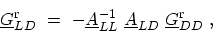 |
(G.8) |
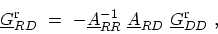 |
(G.9) |
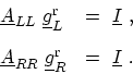
 |
(G.10) |
Substituting (G.8) and (G.9) in (G.10), one obtains a matrix
equation with a dimension corresponding to the total number of grid points in device
layers,
 |
(G.11) |
The second and third terms of (G.11) are self-energies due to coupling of
the device region to left and right contacts, respectively.
The GREEN's functions of the isolated semi-infinite contacts are defined as
 |
(G.12) |
The surface GREEN's function of the left and right contacts are the
GREEN's function elements corresponding to the first edge layer of the respective contact
 |
(G.13) |
M. Pourfath: Numerical Study of Quantum Transport in Carbon Nanotube-Based Transistors