4.1 Decomposition of Geometries and Meshes, Templated Structures
First, decompositions of geometries and meshes are defined. Geometry and mesh decompositions are similar to manifold partitions and mesh partitions, respectively, with the difference that they support multiple regions.
Similar terms can be defined for meshes as well.
Figure 4.2:
Decomposition of a multi-region mesh
|
|
An example of a mesh decomposition is visualized in Figure 4.2.
In general, arbitrary invertible transformation functions  can be used for instances, but it is beneficial to restrict the transformation functions to functions which are angle-preserving. The angle-preserving property is important, because most popular mesh element quality measures are invariant under such transformations.
Therefore, only rigid transformations which are rotations, translations, reflections, and their combinations, are used.
can be used for instances, but it is beneficial to restrict the transformation functions to functions which are angle-preserving. The angle-preserving property is important, because most popular mesh element quality measures are invariant under such transformations.
Therefore, only rigid transformations which are rotations, translations, reflections, and their combinations, are used.
On the contrary, a multi-region geometry (or multi-region mesh) can be defined using a set of templates, each together with a set of transformation functions.
A naive approach is to define the templated structure of a multi-region geometry or mesh as a collection of multi-region templates each with a transformation function for each instance.
However, it is also possible to use templates with only one region to represent a multi-region mesh or geometry.
For each multi-region template in this naive approach, each region can be seen as a template on its own with the same transformation function and an additional region indicator. The resulting templated structure is defined as follows:
![\begin{defn}[Templated structure]
Let $X_1, \dots, X_k$\ be either geometries or...
...}^\star ({\operatorname{us}}(T_{j,h}(X_j))) = \emptyset
\end{equation}\end{defn}](img552.gif)
A templated structure is a collection of templates  , which form multiple instances by using transformation functions
  and region indicators
  . An instance is generated by applying the transformation function
  to the template and using a region indicator function which maps every element of that instance to the corresponding region indicator
  . Therefore, the instance of the template
  with a transformation function
  and a region indicator
  is equal to
 with
with
 .
The advantage of this definition (in contrast to using multi-region templates) is the simplicity of the templates, which have just one region. The boundary patch partition, an instrument to identify and address conformities in templated meshes (see Section 4.3), is much easier to generate, when the templates have one single region.
.
The advantage of this definition (in contrast to using multi-region templates) is the simplicity of the templates, which have just one region. The boundary patch partition, an instrument to identify and address conformities in templated meshes (see Section 4.3), is much easier to generate, when the templates have one single region.
Figure 4.4:
Templated structure with non-conforming structure instance
|
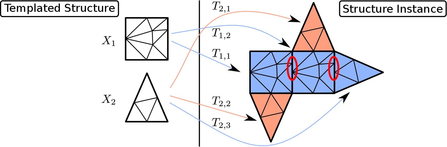
The templated structure is similar to the structure visualized in Figure 4.3 with the difference, that  is just a translation (in contrast of being a combination of a reflection around the y-axis and a translation). This results in a structure instance which is not conforming as indicated by the highlighted red areas. is just a translation (in contrast of being a combination of a reflection around the y-axis and a translation). This results in a structure instance which is not conforming as indicated by the highlighted red areas. |
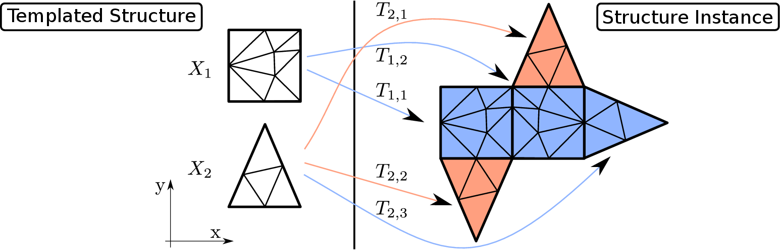
The instance of a templated structure, in short called structure instance, is obtained by using the apply-template operator, which is defined in the following way:
 |
(4.1) |
This operator generates a multi-region geometry or mesh based on the templated structure. A templated structure and its structure instance are visualized in Figure 4.3.
A templated geometry and a templated mesh are templated structures, the structure instances of which result in a valid multi-region geometry or multi-region mesh, respectively.
The structure instance of a templated structure with geometry templates is automatically a valid multi-region geometry.
However, for a templated structure with mesh templates, its structure instance might not be a valid multi-region mesh as visualized in Figure 4.4.
Thus, the additional requirement of
 being a valid multi-region mesh is necessary. The following two statements are equivalent for a templated structure with mesh templates:
- (i)
-
 is a multi-region mesh.
- (ii)
-
 is conforming.
The dimension of a templated structure
 is equal to the dimension of all its templates
 .
.
It is important for templated structures to find out, if a templated mesh is the mesh of a templated geometry. Therefore, the term geometry-conforming is also defined for templated structures.
The motivation for this definition of the term geometry-conforming for templated structures is the direct correlation between the geometry and mesh instances.
For a templated mesh  , which geometry-conforms to a templated geometry
  , all mesh instances are naturally geometry-conforming to the corresponding geometry instances.
Therefore,
, all mesh instances are naturally geometry-conforming to the corresponding geometry instances.
Therefore,
 automatically geometry-conforms to
 .
This definition is also beneficial when formulating mesh adaptation and mesh generation algorithms.
Similar to the geometry of a mesh, the templated geometry of a templated mesh is defined as
.
This definition is also beneficial when formulating mesh adaptation and mesh generation algorithms.
Similar to the geometry of a mesh, the templated geometry of a templated mesh is defined as
 |
(4.2) |
Every templated mesh is naturally geometry-conforming to its templated geometry.
florian
2016-11-21
![\begin{defn}[Geometry-conforming]
A templated mesh ${\Gamma}$\ is called geometr...
...}({\Gamma},i,j) = \operatorname{rid}({\Lambda},i,j)$).
\end{enumerate}\end{defn}](img580.gif)
![\begin{subfigure}
% latex2html id marker 6506
[t]{0.30\textwidth}
\centering
\...
...{figures/mesh_decomposition_whole}
\caption{Multi-region mesh}
\end{subfigure}](img549.gif)
![\begin{subfigure}
% latex2html id marker 6513
[t]{0.30\textwidth}
\centering
\...
...textwidth]{figures/mesh_decomposition}
\caption{Decomposition}
\end{subfigure}](img550.gif)
![\begin{defn}[Templated geometry, templated mesh]
A templated structure ${\mathbb...
...athbb{X}})$\ is a valid multi-region mesh is called a templated mesh.
\end{defn}](img574.gif)