The basic principle of strained-layer epitaxy is that a certain amount of elastic strain can be accommodated by any material without generating
dislocations or defects. It
takes energy to accommodate an epitaxial layer of lattice-mismatched material. The energy depends on both the thickness and the size of the lattice
mismatch. It also requires energy to create a dislocation that will relieve the lattice mismatch strain. If the thickness of the epitaxial layer is kept
small enough to maintain the elastic strain energy below the energy of dislocation formation, the strained-layer structure will be thermodynamically
stable
against dislocation formation. The unstrained state of the lattice-mismatched layer is energetically most favorable, but the strained structure is stable
against transformation to the unstrained state by the energy barrier associated with the generation of enough dislocations to relieve the strain.
The most important types are edge and screw dislocations. Edge dislocation can be represented by an extra half plane inserted into a crystal as
illustrated in Fig. 3.1. The edge of this half plane is called an edge dislocation. In the vicinity of the dislocation the deviation of
Figure 3.1:
Edge dislocation.
|
|
the crystal structure from the ideal one is rather strong. But already at distances of a few lattice periods the crystal planes touch each other almost as
in the
perfect crystal structure. However, the deformation also exists at great distance from the dislocation. It can be clearly found by traversing a closed
contour through the lattice nodes in  plane containing the origin of the coordinates. If
  stands for the displacement of an atom from its
position in the ideal structure, the total change of this vector for the whole contour is not equal to zero. Instead it is equal to the lattice period
along
stands for the displacement of an atom from its
position in the ideal structure, the total change of this vector for the whole contour is not equal to zero. Instead it is equal to the lattice period
along  .
.
Screw dislocations can be viewed as a result of cutting a lattice along a half plane with a subsequent one period relative shift of the two
parts of the lattice on each side of the cut as depicted in Fig. 3.2. The edge of the cut is called the screw dislocation. Traversing a contour
around the
Figure 3.2:
Screw dislocation.
|
|
dislocation line the vector gains one period along this axis. From the macroscopic point of view a dislocation deformation of a crystal
considered as a continuous media has a general property: traversing a closed contour  containing the dislocation line
  , the vector of the elastic
shift gains a finite addition
, the vector of the elastic
shift gains a finite addition  equal to one of the periods of a given crystal lattice. The constant vector is called Burger's
vector of a given dislocation. This property is mathematically written as:
equal to one of the periods of a given crystal lattice. The constant vector is called Burger's
vector of a given dislocation. This property is mathematically written as:
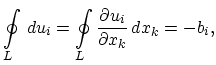 |
(3.1) |
where it is understood that the traversing direction of the contour is clockwise with respect to the chosen direction of the tangent vector
 of the
dislocation line. The dislocation line itself represents a line of peculiar points of the deformation field. In the case of
edge and screw dislocations the dislocation lines represent straight lines with
of the
dislocation line. The dislocation line itself represents a line of peculiar points of the deformation field. In the case of
edge and screw dislocations the dislocation lines represent straight lines with
 and
and
 ,
respectively. In the general case a dislocation is a curve along which the angle between
and can change. A
dislocation line cannot stop inside a crystal. The two ends must be on the surface of a crystal or the dislocation represents a loop. Condition
(3.1) means that the displacement vector is a non-unique function of coordinates. It gains an additional vector after traversing a contour around a
dislocation line. Physically there does not exist any non-uniqueness: an additional vector means an additional one period shift of the lattice
nodes which cannot change the lattice state. In particular, the stress tensor is a unique and continuous function of coordinates.
,
respectively. In the general case a dislocation is a curve along which the angle between
and can change. A
dislocation line cannot stop inside a crystal. The two ends must be on the surface of a crystal or the dislocation represents a loop. Condition
(3.1) means that the displacement vector is a non-unique function of coordinates. It gains an additional vector after traversing a contour around a
dislocation line. Physically there does not exist any non-uniqueness: an additional vector means an additional one period shift of the lattice
nodes which cannot change the lattice state. In particular, the stress tensor is a unique and continuous function of coordinates.
A fundamental assumption underlying many of the critical thickness calculations is the a priori assumption that the equilibrium configuration of the
strain
induced dislocations is that of a regular, non-interacting, rectangular array. Critical layer thicknesses are then computed by requiring that the total
strain energy per unit area
 be a minimum with respect to the in-plane strain
 |
(3.2) |
evaluated at
 , where
  is the mismatch between the film and the substrate. Here
is defined as a sum
is the mismatch between the film and the substrate. Here
is defined as a sum
 |
(3.3) |
of the homogeneous strain energy density
 :
:
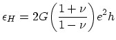 |
(3.4) |
and the areal energy density of the dislocation
 :
:
 |
(3.5) |
Here  is the shear modulus,
  is the film thickness,
  the energy per unit length of a given dislocation line, and
  is the spacing between the dislocations in the assumed rectangular array. It should be noted that is independent of the in-plane strain in the
film [53] and in fact
only depends on the strain in the film through of the strain-dependence of the effective interfacial
width . The spacing between dislocations in the array is given by
is the spacing between the dislocations in the assumed rectangular array. It should be noted that is independent of the in-plane strain in the
film [53] and in fact
only depends on the strain in the film through of the strain-dependence of the effective interfacial
width . The spacing between dislocations in the array is given by
 |
(3.6) |
where  is the magnitude of Burger's vector. Equations (3.4)-(3.6) in conjuction with the mechanical equilibrium condition
(3.2) give the following equation [54] for the critical thickness
is the magnitude of Burger's vector. Equations (3.4)-(3.6) in conjuction with the mechanical equilibrium condition
(3.2) give the following equation [54] for the critical thickness  :
:
![$\displaystyle h_{c}=\frac{b}{4\pi f(1+\nu)}\biggl[\ln\biggl(\frac{h_{c}}{b}\biggr)+1\biggr].$](img658.png) |
(3.7) |
However there are other models for the critical thickness . One of them can be described by the expression [55]:
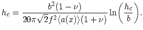 |
(3.8) |
The difference between the models (3.7) and (3.8) lies in the fact that in deriving (3.8)
it is not assumed that initial dislocations appear in a regular rectangular array. Here dislocations are generated in a stochastic fashion. This is an
attempt to deal with the relaxation kinetics in contrast to the equilibrium based derivation (3.7). It is assumed that dislocation
formation
requires in a dislocation formation energy
. As the thickness of a film approaches its critical value, some fraction of the homogeneous
strain energy
will be used to supply this dislocation formation energy.
S. Smirnov:
![\includegraphics[width=0.8\linewidth]{figures/figure_III_1}](img636.png)
![\includegraphics[width=0.6\linewidth]{figures/figure_III_2}](img638.png)