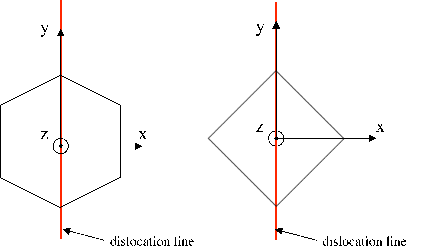
| Figure 3.6: | The z-axis is perpendicular to the c-plane for the hexagonal symmetry and to the closed packed plane for the cubic one. The dislocation line lies along the y-axis in both cases. |
In Section 3.5 the pre-logarithmic coefficient K was calculated as a function of the geometrical parameters α and β using an anisotropic elasticity. In this section, K is calculated using the anisotropic framework for a dislocation lying in the basal plane of AlxGa1-xN and InxGa1-xN, and for a 60∘-dislocation in Si 1-xGex (see Figure 3.6).
| Figure 3.6: | The z-axis is perpendicular to the c-plane for the hexagonal symmetry and to the closed packed plane for the cubic one. The dislocation line lies along the y-axis in both cases. |
The K calculation is performed numerically according to equation (3.41) (dislocation in an infinitely large anisotropic medium, Steeds model [72]) using the software Wolfram Mathematica. Next the results are compared with values obtained with isotropic elasticity (dislocation in an infinitely large isotropic medium) and an atomistic scale computer simulation. The data obtained with atomistic simulations are taken from literature [5,37,42,63]. Table 3.1 shows the comparison of results.
| Table 3.1: | Pre-logarithmic coefficients for some alloys according to the isotropic and anisotropic models. Data from atomistic simulations are included whenever available. |
| material | Si | Si0.5Ge0.5 | In0.2Ga0.8N | Al0.2Ga0.8N | GaN |
| unit of measure | ×10-9 J/m | ×10-9 J/m | ×10-9 J/m | ×10-9 J/m | ×10-9 J/m |
| dislocation | 60∘ dislocation | 60∘ dislocation | ⟨113⟩{101} | ⟨113⟩{101} | (a+c)-type |
| Isotropic elasticity | 1.7 | 1.7 | 5.55 | 5.44 | 5.51 |
| Anisotropic elasticity | 0.56 | 0.52 | 3.53 | 3.95 | 3.94 |
| Atomistic simulation | 0.64 [63] | 3.44 [5] | |||
Table 3.1 shows a good agreement between Steeds’ model [72] and atomistic simulations whenever the data are available in literature. This result is understandable as the atomistic simulations consider a dislocation in an infinite anisotropic structure, which is the same assumption as in Steeds’ model.
The calculations in Section 4.6 require the total energy of the dislocation. To express the total energy of a dislocation, the dislocation core energy needs to be added to the continuum formula for the bulk energy (see equation (3.1)). Based on the above comparison, the continuum approach, including the elastic anisotropy, seems to be compatible with the atomistic evaluation of the dislocation core energy and radius. Consequently, the values of the dislocation core energy obtained with atomistic simulations (listed in Table 3.2) are used to calculate the total dislocation energy in Section 4.6.
| Table 3.2: | Parameters of the dislocation cores from atomistic simulations. 0.43 eV/Å is equal to 0.64 nJ/m. |
| material | dislocation | d core∕dy core∕dy | Pre-logarithmic term | Reference |
| [eV/Å] | [eV/Å] | |||
| Si | 60∘ | 0.43 | [42] | |
| Si0.5Ge0.5 | 60∘ | 0.59 | 0.43 | [63] |
| GaN | (a+c)-type | 3.12 | 2.15 | [5] |
| GaN | a-type | 1.61 | 0.81 | [37] |
| AlN | a-type | 1.71 | 0.90 | [37] |
| InN | a-type | 1.66 | 0.41 | [37] |
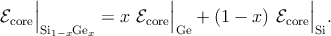
Since the core energy values are available only for certain compositions, the dislocation core energy for each composition of the alloys considered in Section 4.6 is calculated through line interpolation (Vegard-like behavior) of the values summarized in Table 3.2. For example, in the case of Si1-xGex, one gets
 | (3.42) |
The core energy core for Ge is calculated by linearly extrapolating the core energies of Si
and Si0.5Ge0.5. Analogous expressions are also used for AlxGa1-xN and InxGa1-xN.