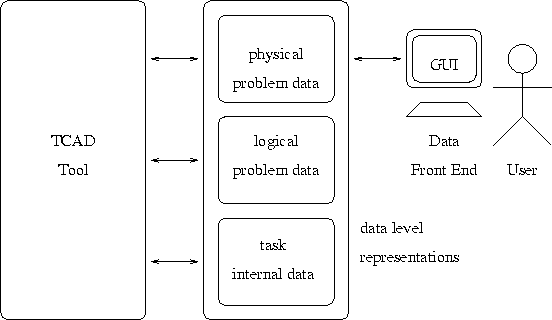
Figure 2.7: The user's ideal view of TCAD data


All the data items seen by a TCAD tool have to be represented consistently on the data level, because an application wants to ``know'' the semantics of what it reads. It simply does not suffice for the application to ``read a real-valued array'', the application wants to ``read the net doping concentration defined on the channel segment'' from the data level. Therefore the data level has to present high-level views of all those ``objects'' to the application. Especially three of those high-level views are of concern: the geometry representation, the grid representation and the quantity representation.
The geometry representation needs to cover both the logical and the physical geometry. Because of the possible ambiguity of a geometry representation itself and the complex interrelationships between the physical and the logical geometry, this representation is not trivial. Therefore semantical restrictions will have to be made on the geometric elements, and the data level has to take care of the semantical correctness of a geometry representation.
It should be noted that most simulators use grids of various kinds as the basis for all distributed quantities they process, and that this multitude of grids hampers the coupling and integration of simulators. Therefore a flexible and consistent grid representation and management is one of the basic preconditions a TCAD data level and the system itself must fulfill. In the following, both discrete and distributed quantities will be called attributes to emphasize the fact that these are always defined upon another object like a grid. The capability of defining attributes on another arbitrary data level object is called attribution mechanism.
From a TCAD system's point of view it is desirable that there is a clear distinction between physical and logical parameters, since the former are ideally the only ones the user should touch (a casual user does not want to bother with simulator specific flags and settings, he just knows the physics of the problem he investigates). Logical parameters should only be necessary for experienced users who need to twiddle around on simulator internals; unfortunately, complex ``pathological'' semiconductor structures often need twiddling of those parameters, to avoid a simulator crash and to just obtain any result at all from the simulator. This ideal view is expressed in Fig. 2.7, where the user sees and edits just the physical problem data, whereas the logical problem data as well as the task internal data (see Section 2.4) remain hidden.

Figure 2.7: The user's ideal view of TCAD data
It seems that the requirements described above are not too difficult to fulfill. However, there are strong semantical implications that have to be considered: What material does a segment consist of? What if a segment is split into various faces? What if a segment contains a hole? Which attributes do belong to a segment? How does a device simulator know which segment is the drain contact of a MOS device? How does a process simulator know what part of the geometry is exposed to physical treatment? - One can be sure that no two conventional simulators treat this semantics in the same way. However, in a TCAD system all integrated simulators have to agree on a smallest common semantical denominator, or the TCAD system has to ensure semantical correctness of the data before and after each simulator run. The implications of this alternative are far-reaching, inducing genuine problems in data level design and simulator integration, which are not due to data representational details or interface design.
Means for coping with these semantical difficulties are:


