3.8.1.2 IELMINI's Model
Considerable research has been done by
IELMINI et al. [205,206,207,208] who describe inelastic
TAT and also take hopping conduction into
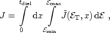
account [209,210]. They derive the trap-assisted current by
an integration along the dielectric thickness and energy
where  denotes the net current flowing through the dielectric,
given as the difference between capture and emission currents through either
side (left or right), as shown in Fig. 3.16
denotes the net current flowing through the dielectric,
given as the difference between capture and emission currents through either
side (left or right), as shown in Fig. 3.16
where
 is the trap occupancy,
 the trap energy,
 the capture
rate, and
the capture
rate, and
 the energy distribution function at the left interface. The
symbol
the energy distribution function at the left interface. The
symbol
 denotes the trap concentration in space and
energy. IELMINI further develops the model to include transient
effects and notes that in this case, the net difference between current from
the left and right interfaces equals the change in the trap occupancy
multiplied by the trap charge
denotes the trap concentration in space and
energy. IELMINI further develops the model to include transient
effects and notes that in this case, the net difference between current from
the left and right interfaces equals the change in the trap occupancy
multiplied by the trap charge
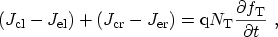 |
(3.125) |
an observation that will be revisited in Section 3.8.2.4. The main
shortcoming of this model, despite its sophistication, is the assumption of a
constant capture cross-section.
Figure 3.16:
Schematic capture and emission currents through
the left and right interfaces of the dielectric layer.
|
|
A. Gehring: Simulation of Tunneling in Semiconductor Devices
![\includegraphics[width=.35\linewidth]{figures/tatCurrents}](img615.png)