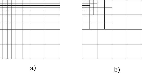
Figure 4.1-1: Typical ortho-product grid used for FD discretizations a) without and b) with terminating grid lines.
Grid generation is one of the most important stages for the whole simulation cycle. Within a simulation environment it is not always necessary to generate a new grid for the current simulation. If the dopant attributes obtained from a previous implantation simulation are defined on a sufficiently dense grid, this grid can be taken as initial grid for the subsequent simulation. Mostly the quality of these given initial grids is rather poor, so we have to redo the grid generation. As a drawback of a newly generated grid should be noted that any ``old'' attribute which should be defined on this new grid must be interpolated, which implies numerical inaccuracies. Generally, interpolation of solution variables should be avoided as long as possible during the simulation flow.
There are several techniques known for grid generation depending on the initial geometry and the PDE discretization methods. Any grid has to fulfill some basic requirements. The grid must resolve the topography accurately to preserve the geometry information. Additionally, the quantities must be resolved sufficiently accurate to minimize discretization errors. Diffusion problems need a dense grid at regions where the diffusion flux varies strongly. The classical way to adapt the grid to the initial quantities is using the first derivation of the initial quantities as adaptation criterion. More accurately refined grids are obtained for the diffusion problem if the mesh is adapted to the curvature of the input quantities.
The problem of the initial grid generation can be divided into a purely geometrical grid generation task, where the grid is generated from the geometry information, and into a grid adaptation or refinement task, where the adaptation to the dopant attributes and the PDE structure is performed.
The conceptually simplest grids are generated for finite-difference (FD) discretization methods. The tensor product grids, which are also known as ortho-product grids, usually can resolve only geometries composed of rectangles, so called Manhattan structures. Figure 4.1-1a shows a conventional tensor product grid, where the grid lines are drawn over the whole structure, even in regions where no high density of grid points is required. This can be avoided by using an ortho-product grid with terminating grid lines (see Fig. 4.1-1b).

Figure 4.1-1: Typical
ortho-product grid used for FD discretizations a) without and b) with
terminating grid lines.
But termination of the grid lines requires special assembling algorithms and destroys immediately the regularity of the structure and the symmetrical properties of the FD resulting linear system [Fra83]. As advantages should be noted that the ortho-product grid allows easy point location operation within the grid and the connectivity information can be obtained by simply increasing or decreasing grid line counters. Also the discretization error, occurring by any spatial discretization method, can be calculated with less effort compared to unstructured grids. When all grid line spacings fulfill special criteria we can describe such grids as quasi-uniform ortho-product grids, which have extremely small discretization errors for the FD discretization. All of the above favored ortho-product grids in the past, were structural issues did not dominate. Till the early 1980's most of the numerical simulators employed in semiconductor analysis used ortho-product grids and FD discretizations [Sel79] [Wim90] [Pic90].
With decreasing device dimensions the global structures became highly nonplanar, even in the active regions of the device. More flexible simulation meshes were needed. It was also of utmost interest to simulate multilayer structures. Therefore, triangular or other element grids gained in acceptance. A triangular grid avoids both drawbacks of ortho-product grids; non rectangular geometries can be approximated very closely with a minimum number of grid points and also the propagation of dense mesh regions is inhibited.
Triangular grids are generated in two different ways:
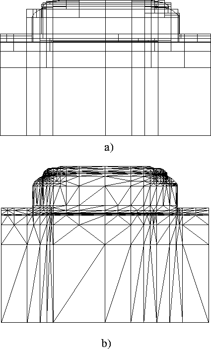
The first method is based on quadtree or even more subtle 2-4 trees. Figure 4.1-2a illustrates the method used for the generation of the quadrangular grid generated by a finite 2-4 tree [Weh95]. Thereby the procedure starts with a super-quadrangle covering the whole simulation geometry. Then the given domain is sub-divided into halves until the geometry is resolved, or as only one geometrical object (line,point) is located in a leaf of the tree. To achieve a triangular grid these quadrangles are finally divided into triangles (see Fig. 4.1-2b).

Figure 4.1-2: Triangular mesh generation using a quadtree for resolving the
geometry: a) gives the quadrangular mesh with only one object in each leaf;
b) shows the final triangular mesh resulting by diagonal and terminating
leaf refinement (1686 grid nodes).
Special geometrical operations like boundary smoothing are necessary to avoid unnecessary high grid density at slanting intersections or triple points [Sah93]. The resulting final triangular grid can be used in any case for FEM discretization methods and for BM as the grid fulfills the ``Delaunay''-criterion.
The Delaunay-criterion can be defined as follows: Every point within a
point-cloud has a unique cell around it. This cell is delimited by so-called
Voronoi points and Voronoi edges. Let us assume a finite set of
points ![]() which are part of a sub-domain
which are part of a sub-domain
![]() of the dimensional space
of the dimensional space ![]() . Two points
. Two points ![]() and
and
![]() are connected by a Delaunay edge, if and only if there is a point
are connected by a Delaunay edge, if and only if there is a point
![]()
![]()
![]() which is equally close to
which is equally close to ![]() and
and ![]() than to any other point
than to any other point ![]() . From this definition
the perpendicular bisectors of the Delaunay edges are related to the Voronoi
points, which are the intersections of these bisectors. The Voronoi nodes
are also given by the circumcenter of the grid triangles. This cellular
decomposition is known as Voronoi tessellation and the dual grid formed by
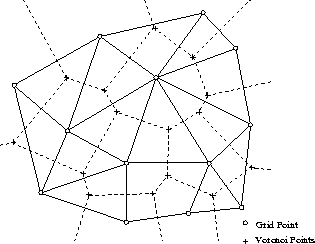
the Voronoi nodes is known as Voronoi grid. Figure 4.1-3 gives
the original triangular grid (solid lines) and the dual Voronoi grid (dashed
lines). If the resulting Voronoi cells can describe the whole simulation
domain without overlapping regions and holes, this grid is referred to as
Delaunay grid and can be used for the box-integration method.
. From this definition
the perpendicular bisectors of the Delaunay edges are related to the Voronoi
points, which are the intersections of these bisectors. The Voronoi nodes
are also given by the circumcenter of the grid triangles. This cellular
decomposition is known as Voronoi tessellation and the dual grid formed by
the Voronoi nodes is known as Voronoi grid. Figure 4.1-3 gives
the original triangular grid (solid lines) and the dual Voronoi grid (dashed
lines). If the resulting Voronoi cells can describe the whole simulation
domain without overlapping regions and holes, this grid is referred to as
Delaunay grid and can be used for the box-integration method.

Figure 4.1-3: Triangular grid
which fulfills Delaunay-criterion (solid lines) and its dual Voronoi grid
(dashed lines) for a given set grid points.
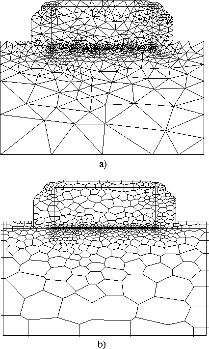
The other way to generate a triangular grid is to refine triangles iteratively. Thereby the grid is generated by a ``divide-and-conquer'' method, where the initial triangulation starts at the geometry boundaries. After the shortest geometry line is extracted, we subdivide this line to generate the first outer grid points. Then the neighboring line is selected for subdivision until all geometry boundary lines are taken. After the boundary grid points are generated the algorithm starts to triangulate the bulk regions. Therefore, one boundary line is selected again and the according inner point is calculated to form a well-shaped triangle (well-shaped means in terms of grid generation no obtuse angle), then the next line is taken and the next inner triangle is formed until the whole domain is resolved. Some quality criteria ensure relatively satisfying quality of the generated triangles. Figure 4.1-4 shows a triangular grid generated by the TRIGEN grid generator program [Ban94], where Figure 4.1-5 gives a triangular Delaunay grid and the according Voronoi grid obtained by the TRIANGLE grid generation program [She96]. The density of the grids can be controlled through the triangle areas or triangle edge size criteria.

Figure 4.1-4: Triangular grid
generated by divide-and-conquer algorithm from TRIGEN. TRIGEN needs 2951 triangles to resolve a ![]() gate oxide.
gate oxide.

Figure 4.1-5: Triangular grid (a)
generated by divide-and-conquer algorithms from TRIANGLE and the
according Voronoi grid (b). TRIANGLE needs 1629 triangles to resolve a
![]() gate oxide.
gate oxide.
The above presented grids resolve only the geometry information by a triangular grid. On the other hand the relevant initial quantities (doping, potential, stress information) have also to be resolved by the triangular grid. The quality of the adaptation procedure affects the subsequent solution of the equation system significantly. Therefore, the geometry mesh must be refined until the desired grid point density is reached.