6.2.2 Three-Dimensional Render Visualization
An essential ability of simulations in the general field of CSE is to visualize simulation results.
Therefore, special consideration has been given to provide a flexible three-dimensional rendering
backend .
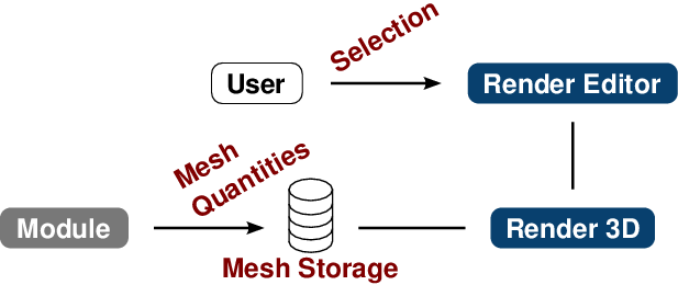
To this end the FLOSS-based VTK library is utilized as a visualization backend of a dedicated
rendering class(Section 2.3), directly utilizable in Qt-based GUI applications. The rendering
class provides an interface for ViennaMOS and its modules to the VTK-based visualization
backend. Also, a render editor GUI is available, providing the advanced users the ability to
customize the rendering (Figure 6.5). Note that the central VTK-based mesh storage is not
related to the previously introduced ViennaMOS communication database. The mesh storage
is solely used for the VTK-based visualization and is thus enforced to be a VTK object.
Therefore, no generic storage - as provided by the ViennaMOS’ communication
database - is required, otherwise unnecessarily complicating the mesh storage
access.
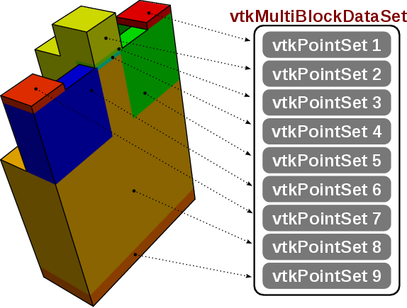
As already indicated, the support for multi-segment meshes is essential for a
simulation framework, as different areas of a simulation domain might require a
different handling. For instance, different materials might be assigned to the individual
segments.
Although using a multi-segment mesh for visualization is not required - as a multi-segment
mesh can also be mapped to a single-segment mesh - it allows to provide segment-specific
visualization options, such as segment-wise coloring or visibility adjustments. These features
further improve usability, as, for instance, the framework can aid the end user in identifying
individual segments of a mesh, especially important for intricate simulation devices. To this
end we use VTK’s vtkMultiBlockDataSet data structure, enabling to hold an arbitrary set of
VTK meshes, such as vtkUnstructuredGrid and vtkStructuredGrid (Figure 6.6). For each
mesh segment, a vtkActor and a vtkDataSetMapper is stored, allowing to perform
segment-specific visualization tasks, such as coloring according to vertex-based scalar
fields.
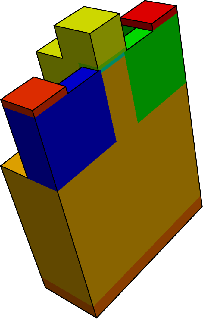
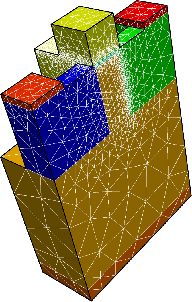
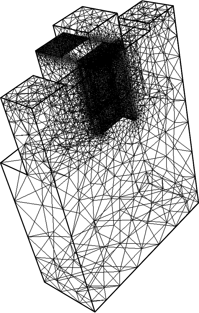
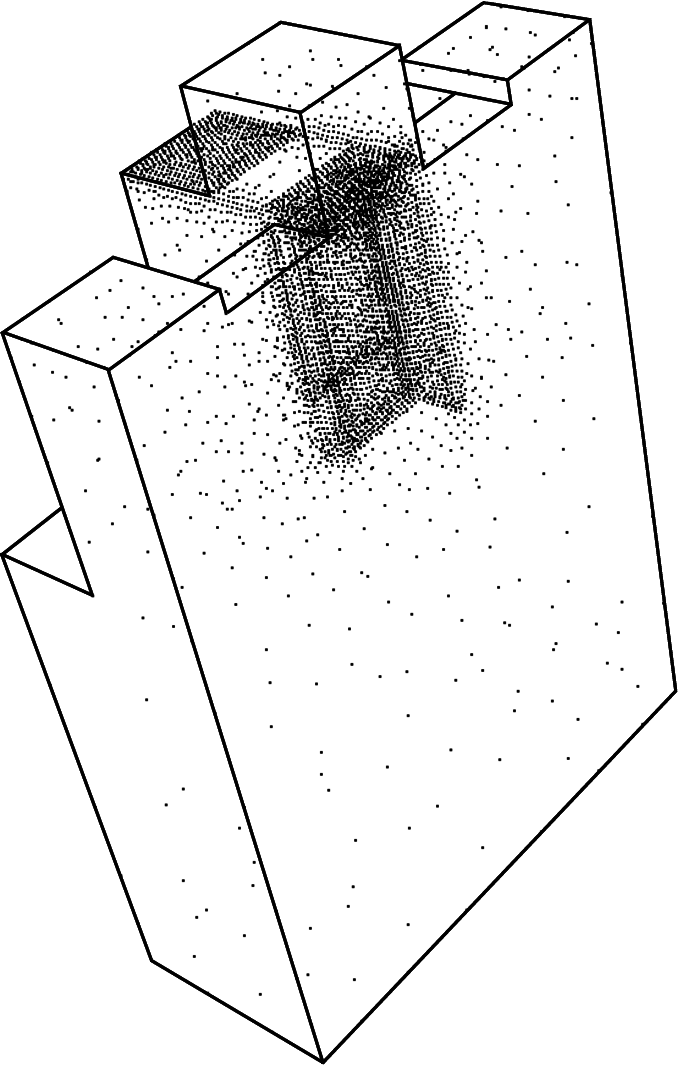
Different mesh representations are supported natively by the VTK library, in particular
surface, surface with edges, wireframe, and point representations, enabled by using the
corresponding vtkActor methods (Figure 6.7).
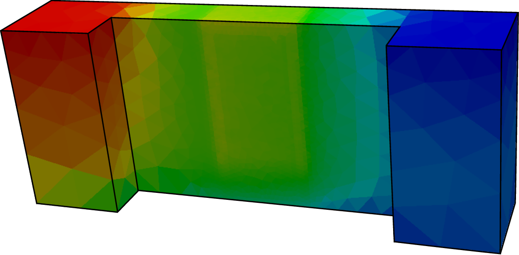
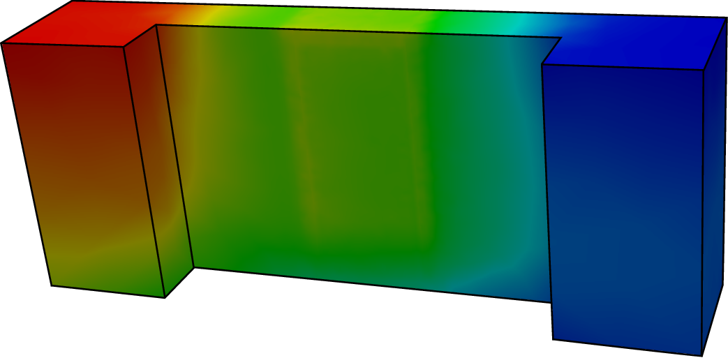
Visualizing data fields on top of meshes requires the data to be stored on the respective
vtkPointSet objects - representing mesh segments - collectively governed in the central
vtkMultiBlockDataSet object. In particular, the data fields have to be stored as
vtkDataArray objects and linked to the corresponding vtkPointSet’s point or cell data
container. Note that VTK natively only supports point or cell data. Due to the support for
mapping data fields on different mesh elements, specific meta information is required by the
render class indicating, for instance, the mesh element association of a particular data set,
i.e., whether the data to be visualized has to be mapped on vertices or on cells. Overall,
ViennaMOS supports cell-based and vertex-based quantity visualization of scalar fields
(Figure 6.8).
Simulation tools might generate a series of simulation results. For instance, simulating the
characteristics of a device yields for each applied bias not only the current at the terminal, but
also the actual quantity distributions, like potential, electron carrier, and hole carrier
distributions. Therefore a playback mechanism has been implemented allowing to step
through the individual simulation results. More concretely, all results are stored on the
multi-block data structures associated with a unique ID relating to the sequence position of the
result. ViennaMOS can thus order the renderer to show a specific result out of a sequence
via generating the corresponding ID. This mechanism not only allows to step forward
and backward, but also enables ViennaMOS to provide an automatic playback
mechanism enslaved to a time-delay used between rendering the individual simulation
result.