
 |
|
||||
Biography
Mario Bendra was born in 1993 in Steyr, Austria. He received his BSc degree in Mechanical Engineering from the University of Applied Sciences Upper Austria in 2017. After an exchange semester at the University of the Sunshine Coast, Australia in 2018, he received the degree of Diplomingenieur in Mechanical Engineering from the University of Applied Sciences Upper Austria in 2019. Mario joined the Institute for Microelectronics in October 2020, where he is working towards his doctoral degree focusing on developing and implementing advanced computational approaches to simulate and optimize spin-transfer torque magnetoresistive memories. |
|||||
Design Support for Interface Effects in Ultra-scaled MRAM Cells
The design of advanced single-digit nanometer footprint MRAM cells requires precise knowledge of spin currents and torques in magnetic tunnel junctions (MTJs) with elongated free and reference layers. Interface-induced effects, like the perpendicular anisotropy and the spin-transfer torque, must be carefully evaluated. For this purpose, we have modeled the interface effects using position-dependent parameters, and applied them to a device with several tunnel barrier interfaces a few nanometers in diameter. The predicted switching behavior of ultra-scaled MRAM cells with several MgO interfaces agrees with recent experiments. A conventional MRAM cell consists of several layers, including a CoFeB reference layer (RL) and a free magnetic layer (FL), separated by a MgO tunnel barrier (TB) or by a nonmagnetic spacer (NMS), c.f. Fig. 1, (b) and (c). The magnetization configuration perpendicular to the TB is determined by the anisotropy induced by the interface at the CoFeB|MgO interface. To further increase the perpendicular magnetic anisotropy, additional CoFeB|MgO interfaces are added in the FL, c.f. Fig. 1(a). To reduce the cell diameter and to further boost the perpendicular anisotropy, one elongates the FL along the direction normal to the CoFeB|MgO interfaces. With the length of the FL increasing to the order of, or even larger than, the diameter of the FL, the shape anisotropy becomes an important contribution to the perpendicular anisotropy. However, the interface-induced anisotropy still plays a decisive role in defining the switching of elongated composite FLs made of several pieces, separated by MgO barriers.
To demonstrate this behavior, we model the interface-induced anisotropy as (i) an average constant contribution to the uniaxial bulk anisotropy (Fig. 2(a), red-dashed line), and as (ii) localized near the interface (Fig. 2(a), solid blue line). We also consider two different behaviors for the transverse spin dephasing length shown in Fig. 2(b). The value of the spin dephasing length determines the characteristic distance over which the non-equilibrium spin accumulation, due to the electric current running through the structure, decays from its maximum value at the FL interface to zero inside the FL. Therefore, the spin dephasing length defines the size of the layer close to the FL interface where the STT is acting. A short value of the dephasing length near the interface (Fig. 2(b), dot-dashed line) agrees with values in MTJs, ensures rapid absorption of the transverse spin components, and localizes the torques at the interfaces. In reality, the spin dephasing length increases away from the interfaces (Fig. 2(b), blue line), allowing torques to act on larger portions of the FL.
There is a distinct peculiarity on the switching curves for both AP to P switching. Namely, the magnetization of the FL develops a plateau around mx = 0. The plateau is due to the fact that the magnetization of the two similar parts composing the FL are anti-parallel to each other. It then follows that the magnetization reversal is a sequential process in which one part of the FL switches first, followed by the magnetization reversal of the remaining part. Fig. 3(a) demonstrates the switching trajectories for the respective magnetization components for the AP to P process. Fig. 3(b) shows the magnetization trajectory on a unit sphere.
This design approach to ultra-scaled STT-MRAM consisting of several elongated pieces of ferromagnets separated by multiple tunnel barriers showed the influence of these effects on the magnetization dynamics and their role in improving the switching behavior in ultra-scaled MRAM cells.
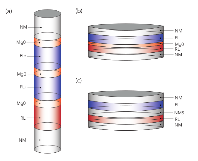
Fig. 1: Schematics: (a) Ultra-scaled MRAM cell with a diameter of 2.3 nm, made of a 5 nm RL, a 0.9 nm TB, and a composite FL, consisting of two ferromagnetic parts separated by a 0.9 nm MgO layer. The FL is capped by an additional MGO layer of 0.9 nm thickness. (b) Conventional MRAM cell with a diameter of 40 nm, made of a 1 nm RL, a 1.7 nm FL, and a 1 nm TB or (c) a NMS which consists of a 2 nm metal film.
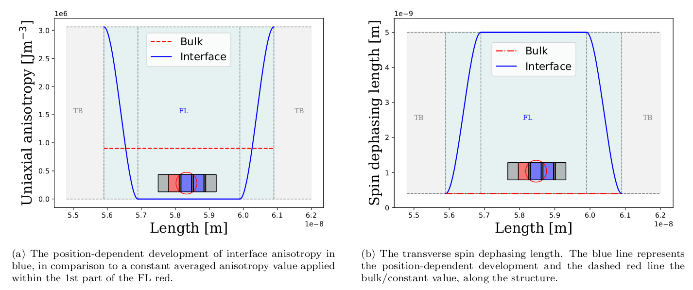
Fig. 2: Interface-induced perpendicular anisotropy and the transverse spin dephasing length.
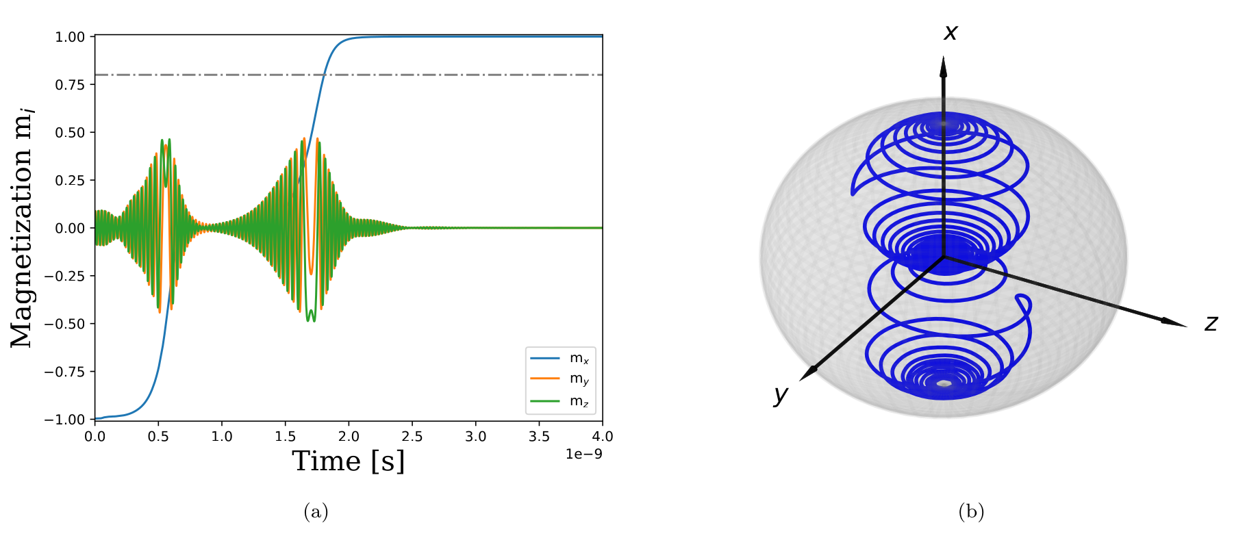
Fig. 3: Magnetization trajectories for switching from AP to P (a) and the trajectory on a unit sphere during AP to P switching (b).