
 |
|
||||
BiographyMario Bendra was born in 1993 in Steyr, Austria. He received his BSc degree in Mechanical Engineering from the University of Applied Sciences Upper Austria in 2017. After an exchange semester at the University of the Sunshine Coast, Australia in 2018, he received the degree of Diplomingenieur in Mechanical Engineering from the University of Applied Sciences Upper Austria in 2019. Mario joined the Institute for Microelectronics in October 2020, where he is working towards his doctoral degree focusing on developing and implementing advanced computational approaches to simulate and optimize spin-transfer torque magnetoresistive memories. |
|||||
Magnetic Tunnel Junctions with Double Spin Torque and Synthetic Antiferromagnetic Layers
Developing subnanosecond magnetic tunnel junctions (MTJs) is critical for next-generation nonvolatile memory, with broad implications for computing, automotive, and storage technologies. Double spin torque MTJs (dsMTJs) offer enhanced performance by incorporating a second reference layer (RL) separated by a nonmagnetic spacer (NMS), improving switching behavior.
Traditionally, MTJ stacks are simplified by modeling the RL as a single layer. To better reflect real-world designs, we introduced SAF structures: a CoPt SAF for the lower RL1 and a CoFeB SAF for the upper RL2, each composed of a hard layer (HL) and RL separated by an NMS, as shown in Fig. 1(a).
Using a fully three-dimensional finite element model that couples drift-diffusion with the Landau Lifshitz Gilbert equation, we explored how interlayer exchange coupling (IEC) influences dsMTJ performance. IEC strength and nature, ferromagnetic (FM) or antiferromagnetic (AFM), depending on the NMS material and thickness, behavior based on Ruderman Kittel Kasuya Yosida (RKKY) interactions.
Our simulations (Fig. 1(b) and Fig. 1(c)) show that optimal performance for parallel to anti-parallel switching is achieved with a Ru NMS at 1 nm (AFM coupling of 0.65 mJm-2) and with a Ta NMS at 0.25 nm (FM coupling of 0.4 mJm-2). Although a Ru NMS at 0.4 nm exhibited the fastest switching, its strong AFM coupling (2.1 mJm-2) prevented complete switching in the anti-parallel to parallel switching.
Finally, we evaluated spin torque distributions when introducing SAF layers into both RL1 and RL2 (Fig. 1 (c)). Ru NMS layers provided greater torque due to their longer spin-flip length (4 nm), reducing spin decay compared to Ta (1.9 nm) and supporting more efficient switching.
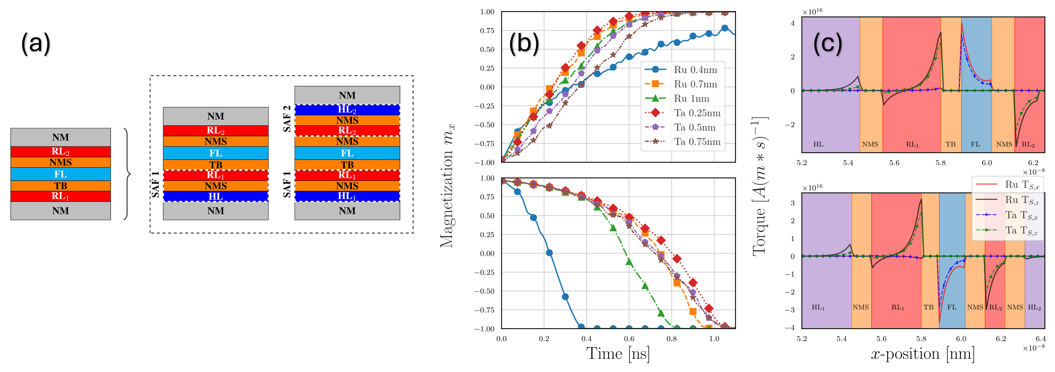
Fig. 1: (a) Illustration of a dsMTJ multilayer device design. The primary structure is shown on the left, while the two variations in the dashed box on the right replace RL1 and RL2 with SAF layers, respectively. Color coding: red for RL, cyan for the free layer, orange for the tunnel barrier and the NMS, purple for the HL, and gray for non-magnetic contacts. (b) Switching durations for dsMTJ devices utilizing a Ru/Ta NMS under varying NMS thicknesses and IEC. (c) Spin torque applied to two configurations: (top) the structure in panel (a) left, and (bottom) the variations in panel (a) right. Black arrows indicate magnetization directions in ferromagnetic layers. TS,x represents the field-like torque along the central axis, and TS,z denotes the damping-like torque component.