Next: 3.8 Numerical Handling of
Up: 3. Diffusion Phenomena in
Previous: 3.6 The Plus-One Model
During ion implementation simple point defect aggregate
to build extended defects such as  defects and dislocation loops.
Clustering of dopants occurs always when the peak of the implants dose exceeds the solid solubility.
Clustered dopants are electrically inactive and immobile and on such way they significantly influence dopant diffusion.
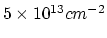
Even at small implant dose a build up of the interstitial
clusters takes place, but the dynamics of the interstitals clusters
significantly increases for an implant dose larger than
defects and dislocation loops.
Clustering of dopants occurs always when the peak of the implants dose exceeds the solid solubility.
Clustered dopants are electrically inactive and immobile and on such way they significantly influence dopant diffusion.
Even at small implant dose a build up of the interstitial
clusters takes place, but the dynamics of the interstitals clusters
significantly increases for an implant dose larger than
 as so-called begin to evolve.
These defects can be described as rod-like in shape running in
as so-called begin to evolve.
These defects can be described as rod-like in shape running in  directions.
If the anneal temperature is larger than
directions.
If the anneal temperature is larger than
 ,
the defects which consist of
,
the defects which consist of  or more interstitials unfalts to
form dislocations loops.
The clusters of dopants and point defects do not evolve individually, but they also interact with each other.
It is possible [36] to model all these defects together with their
dynamics in a consistent and fundamental way within a general framework.
The so called moment-based approach models the size
distribution of dopant and point defect clusters. In this section we
will illustrate moment approach for the case of extended defects and phosphorus diffusion.
or more interstitials unfalts to
form dislocations loops.
The clusters of dopants and point defects do not evolve individually, but they also interact with each other.
It is possible [36] to model all these defects together with their
dynamics in a consistent and fundamental way within a general framework.
The so called moment-based approach models the size
distribution of dopant and point defect clusters. In this section we
will illustrate moment approach for the case of extended defects and phosphorus diffusion.
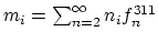
The central role in the moment approach plays the size
distribution function
 of the extended defects.
This distribution function determines the density per unit volume of extended defects consisting of
of the extended defects.
This distribution function determines the density per unit volume of extended defects consisting of  interstitials at a given location and time.
The behavior of defects is described with the following equations which deal with the moments of the distribution
interstitials at a given location and time.
The behavior of defects is described with the following equations which deal with the moments of the distribution  ,
,
 [36,30].
![$\displaystyle \frac{\partial m_0}{\partial t}=D \lambda[(C_I^{311})^2-m_0C_{ss}\gamma_0],$](img417.png) |
(3.69) |
![$\displaystyle \frac{\partial m_1}{\partial t}=2\frac{\partial m_0}{\partial t}+ D \lambda m_0[C_I^{311}-m_0C_{ss}\gamma_1],$](img418.png) |
(3.70) |
 |
(3.71) |
with,
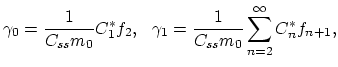 |
(3.72) |
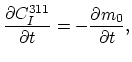
where  is the concentration of the interstitials bound in extended defects,
  is the solid solubility and
  is the interstitial concentration at which there will be no change in the free energy for precipitates to grow from size to
  .
.
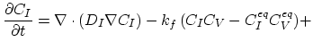
This model for extended defects can be readily combined with the three stream Mulavaney-Richardson model in order to get an equation set which describes dopant behavior in the presence of interstitial clusters.
Since boron diffuses primarily through pairing with interstitals one can omit the vacancy-dopant term from the first and third equation of the model.
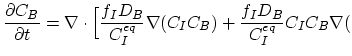 ln ln![$\displaystyle n)\Bigr],$](img352.png) |
(3.73) |
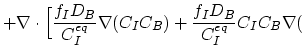 ln ln![$\displaystyle n)\Bigr]-\frac{\partial C_I^{311}}{\partial t},$](img427.png) |
(3.74) |
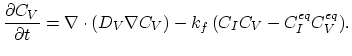 |
(3.75) |
As shown in [37], this kind of model is suitable to simulate diffusion which controls the junction depth for ultra-low energy boron implants.
Next: 3.8 Numerical Handling of
Up: 3. Diffusion Phenomena in
Previous: 3.6 The Plus-One Model
H. Ceric: Numerical Techniques in Modern TCAD