

Next: 4.1.2 PDE Method
Up: 4.1 Structured Grid Generation
Previous: 4.1 Structured Grid Generation
The parametrized boundary surfaces are algebraically combined to create the
interior grid. The mapping of the unit square/cube with coordinates  onto the domain is performed by the transfinite interpolation [184].
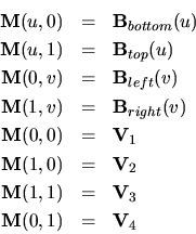
In two dimensions it can be written as
where  are the boundaries,
  the four corner vertices,
and
  is the mapping function to calculate the coordinates
  in
the real domain. The mapping function satisfies
The resulting grid is useful if the boundaries are convex or not too
twisted. A three-dimensional example of the mesh of a LOCOS which was
generated with a package described in [13] is shown in Fig. 4.2-a.
Figure 4.2:
LOCOS: (a) structured mesh, 2000 tetrahedra (b) unstructured
mesh, 957 tetrahedra.
|
|
Peter Fleischmann
2000-01-20
![]() onto the domain is performed by the transfinite interpolation [184].
In two dimensions it can be written as
onto the domain is performed by the transfinite interpolation [184].
In two dimensions it can be written as

