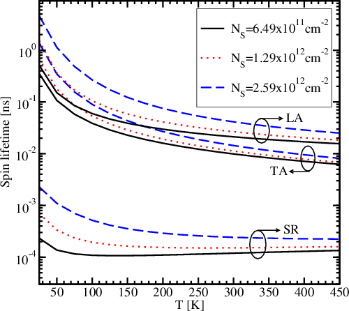
The observed spin lifetime in unstrained thin films is much different compared
to bulk samples. Experiments show a dramatic reduction of the spin relaxation
time in Si/SiO
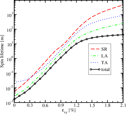
4.4.1 Spin Lifetime Enhancement with Shear Strain
Figure 4.11 shows the contributions of the surface roughness (
4.4.2 Inter- and Intrasubband Components
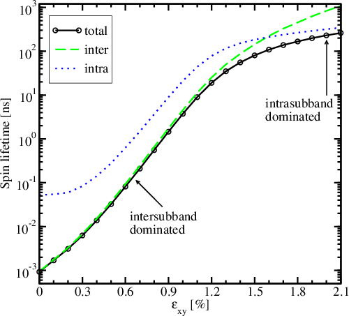
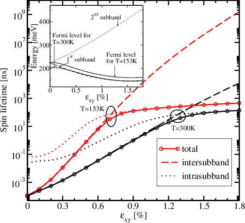
In order to elucidate the spin relaxation mechanism, the spin-flip caused by
the intra- and intersubband scattering must be analyzed. The corresponding
components of the spin lifetime at the room temperature (RT) for a sample
thickness of
Figure 4.14 delineates the surface roughness induced spin relaxation time with
its inter- and intrasubband components at two distinct temperatures and at a
very low sample thickness. One can see that, when the temperature decreases the
Fermi level energy increases (c.f. Figure 4.14 inset), the intersubband scattering
becomes less efficient already at lower values of the shear strain component
4.4.3 Effect of Spin Injection Orientation
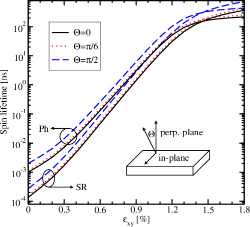
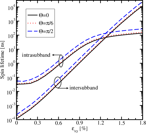
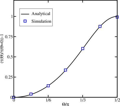
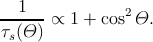
Figure 4.15 shows how the surface roughness and the phonon mediated
components of the total spin lifetime (denoted as
Now, one needs to investigate the dependence of the total spin lifetime
 | (4.37) |
In such a condition,
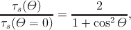 | (4.38) |
and therefore,
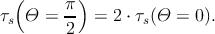 | (4.39) |
So, the total spin lifetime