5.3.1 The Simplex Idea


Next: Generalized Coordinates
Up: 5.3 Data Structures
Previous: 5.3 Data Structures
For the conceptual characterization of the data structures and
operations of the VISTA visualization, the notion of simplexes
is used.
We call a  -dimensional simplex
 or
or  -simplex ``the most simple'' finite
  -dimensional geometrical
object defined by

 -dimensional sub-simplexes
A zero-dimensional geometrical object is a point.
According to this definition,
a single point is a zero-simplex; it is
obviously the only zero-dimensional geometrical object.
A straight line segment is a
one-simplex; it is the simplest one-dimensional geometrical
object. A planar triangle, bounded by three straight line
segments is a two-simplex; it is again the simplest two-dimensional
finite geometrical object. This recursive hierarchical construction
can be formally continued to arbitrary simplex dimensions.
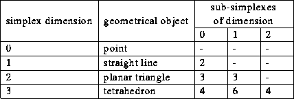
Table 5.3.1 gives an overview of all practically relevant
simplexes.
Leaving performance and compatibility issues entirely out of considerations,
the mere fact that
the triangle is a basic primitive of modern graphics hardware for
three-dimensional problems confirms that
the simplex approach is a sound and feasible choice for the
efficient representation of visualizable data.

Table 5.1: Simplex objects and their constituent sub-simplexes
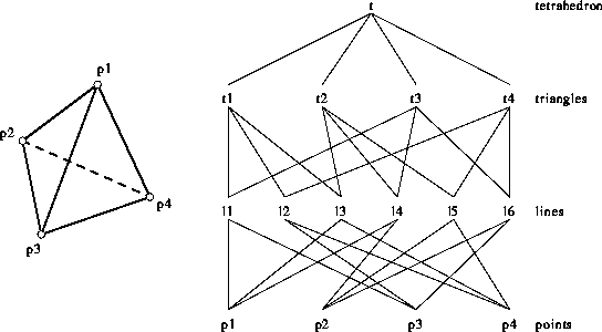
Figure 5.1 shows a three-simplex and its sub-simplexes. The
tetrahedron consists of four planar triangles, which consist of
six distinct straight lines, which in turn consist of four
distinct points.

Figure 5.1: A 3-simplex (a tetrahedron) consists of
four 2-simplexes (triangles),
six 1-simplexes (lines), and four 0-simplexes (points).
A mechanism to attach visual properties to the simplexes and to
proliferate and process this information is required.
This is done by an integer attribute that can be
assigned to every simplex. This integer
attribute is used as index
for visual properties (like line style, color, or texture) in the output
modules as the mapping depends on the capabilities of the
output device. The value of
the simplex attributes
can be set and changed
in the visualization modules, depending on geometrical or
non-geometrical information. For example, to visualize a
quantity together with its tensor-product mesh, the mesh must be
decomposed into triangles but the resulting artificial diagonal edges
should not appear in the final visible output. So the (PIF)
input module sets the attribute of the diagonal lines (1-simplexes) to
``invisible''. This information then propagates unchanged through all
intermediate operations to the output module which does not draw the
artificial diagonals.


Next: Generalized Coordinates
Up: 5.3 Data Structures
Previous: 5.3 Data Structures
Martin Stiftinger
Thu Oct 13 13:51:43 MET 1994
 -dimensional simplex
 or
or  -simplex ``the most simple'' finite
  -dimensional geometrical
object defined by

 -dimensional sub-simplexes
A zero-dimensional geometrical object is a point.
According to this definition,
a single point is a zero-simplex; it is
obviously the only zero-dimensional geometrical object.
A straight line segment is a
one-simplex; it is the simplest one-dimensional geometrical
object. A planar triangle, bounded by three straight line
segments is a two-simplex; it is again the simplest two-dimensional
finite geometrical object. This recursive hierarchical construction
can be formally continued to arbitrary simplex dimensions.
Table 5.3.1 gives an overview of all practically relevant
simplexes.


