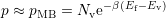
8.1 Rate Equations
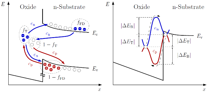
Based on the existence of oxide defects and the band-to-trap transition
possibilities, depicted in Fig. 8.1, already a single defect system has to consider
all transitions originating from various band states. This means that the whole
conduction or valence band has to be considered, instead of only  or
or
 . On the basis of the statistical description of the recombination of
electrons and holes under the release of energy in terms of lattice vibrations
(Shockley-Read-Hall theory [122]), the determination of effective rates in and out
of a specific defect system is possible. The corresponding rate equations are
. On the basis of the statistical description of the recombination of
electrons and holes under the release of energy in terms of lattice vibrations
(Shockley-Read-Hall theory [122]), the determination of effective rates in and out
of a specific defect system is possible. The corresponding rate equations are
with the trap occupancy in the oxide  and the Fermi-Dirac distribution
  ,
which represents the probability of an occupied quantum state in the substrate.
Since the Fermi-Dirac distribution is valid in thermal equilibrium and still a very
good approximation during BTI, as there is nearly no channel current
[129, 130], the distributions write as
,
which represents the probability of an occupied quantum state in the substrate.
Since the Fermi-Dirac distribution is valid in thermal equilibrium and still a very
good approximation during BTI, as there is nearly no channel current
[129, 130], the distributions write as  and
and
 . The quantities
  ,
,  ,
,  , and
, and  stand for
the coefficients of electron capture, electron emission, hole emission, and hole
capture. The density of states (DOS) is split into a conduction band part
stand for
the coefficients of electron capture, electron emission, hole emission, and hole
capture. The density of states (DOS) is split into a conduction band part  and a valence band part
  .
.
Assuming detailed balance [122], which means that each process is balanced
by its reverse process, both rates have to equal within (8.1) and (8.2). This
yields
 | (8.3) |
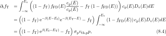
Combining (8.3) with (8.2)
and evaluating the integral finally gives the capture time constant  of the
holes
of the
holes
with the cross section  and thermal velocity
  of the holes with density
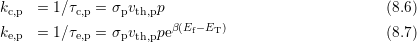
 . The term outside the brackets can be identified as the capture rate, which
can be seen when (8.4) is compared to the simple rate equation of a two-state
defect
. The term outside the brackets can be identified as the capture rate, which
can be seen when (8.4) is compared to the simple rate equation of a two-state
defect
 | (8.5) |
with the rate  to fill the defect at
  and
and  for the reverse rate.
Furthermore,
for the reverse rate.
Furthermore,  gives the probability that the defect is actually filled.
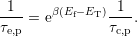
Consequently, the capture and emission rates can be written as
gives the probability that the defect is actually filled.
Consequently, the capture and emission rates can be written as
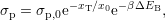
or as the relation
In addition to a tunneling coefficient of  to account for the oxide
trap depth after [121], the cross section is considered to be thermally activated
with a bias independent barrier
to account for the oxide
trap depth after [121], the cross section is considered to be thermally activated
with a bias independent barrier  [124]. Putting these assumptions together
yields
[124]. Putting these assumptions together
yields
 | (8.8) |
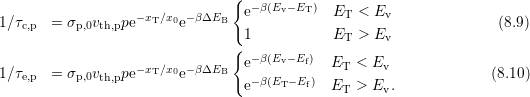
with a constant prefactor  [131, 124]. With the knowledge that whether the
defect level lies below or above
[131, 124]. With the knowledge that whether the
defect level lies below or above  , different barriers are obtained after
Fig. 8.1, equations (8.6) to (8.8) are now used to calculate the capture rates
, different barriers are obtained after
Fig. 8.1, equations (8.6) to (8.8) are now used to calculate the capture rates
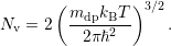
As thermal equilibrium is assumed and the density of states is low enough to rule
out quantum effects, the Fermi-Dirac-distribution can be replaced by the
Maxwell–Boltzmann-distribution [10]
 | (8.11) |
with  as effective valence band weight,
The trapping barrier  can further be written as a superposition of the
energy distance during flatband
can further be written as a superposition of the
energy distance during flatband  and the applied field
  which changes the relative barrier between semiconductor and oxide, cf. Fig. 8.1
(right) and Fig. 8.2 (right)
which changes the relative barrier between semiconductor and oxide, cf. Fig. 8.1
(right) and Fig. 8.2 (right)
 | (8.12) |
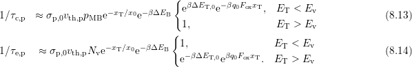
With the help of (8.11) and (8.12) the time constants in (8.9) and (8.10) finally
read as
At first only the part of (8.13) and (8.14), which depends on the relative position
of  to
to  is discussed. The temperature dependence here is dominated by
the thermal barrier
is discussed. The temperature dependence here is dominated by
the thermal barrier  . While the barrier
  determines hole capture
when
determines hole capture
when  holds, the barrier
  contributes to hole emission only
when
contributes to hole emission only
when  . So the barriers are either relevant for
  or
or  and do not
affect both rates. This is due to the relative position of the energetic defect level
and its reservoir, as depicted in Fig. 8.1 (left). When looking at the term
and do not
affect both rates. This is due to the relative position of the energetic defect level
and its reservoir, as depicted in Fig. 8.1 (left). When looking at the term
 , it can be seen that the applied field either lowers
or rises the barrier, but again the field dependence is only included in
either
, it can be seen that the applied field either lowers
or rises the barrier, but again the field dependence is only included in
either  or
or  . Additional bias dependencies arise from the surface
hole concentration, especially below
. Additional bias dependencies arise from the surface
hole concentration, especially below  , and the tunneling coefficient
[130].
, and the tunneling coefficient
[130].
In a typical BTI stress/relaxation sequence all defects are in thermal
equilibrium prior to stress. Due to stress the Fermi level  is shifted
below
is shifted
below  . For defects with
  the resulting barrier
  can
only be balanced by the
can
only be balanced by the  term in (8.13). After (8.12) this means
that energetically deeper defects also need to be located deeper in the
oxide in order to become charged during stress, i.e. only defects with
term in (8.13). After (8.12) this means
that energetically deeper defects also need to be located deeper in the
oxide in order to become charged during stress, i.e. only defects with
 , where
  denotes the potential at the interface,
are accessible during stress [130]. When the stress is completely removed,
denotes the potential at the interface,
are accessible during stress [130]. When the stress is completely removed,  is shifted back above
  and the previously charged defects will by
moved back below
and the previously charged defects will by
moved back below  . According to (8.14) they can be emptied over a
small barrier if there is any. Thereby accessible oxide defects now feature
. According to (8.14) they can be emptied over a
small barrier if there is any. Thereby accessible oxide defects now feature
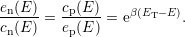
 during relaxation [130]. Thus, the exact defect level
is not of particular interest for the capture and emission process.
during relaxation [130]. Thus, the exact defect level
is not of particular interest for the capture and emission process.  only has to lie inside the accessible energy region, i.e. above
  for
stress and below
for
stress and below  for relaxation. This means that the conditional
part of (8.13) and (8.14) only exhibits a small temperature and field
dependence.
for relaxation. This means that the conditional
part of (8.13) and (8.14) only exhibits a small temperature and field
dependence.
It is important to realize that it is the thermal barrier  in (8.13) and
(8.14) introduced by Kirton and Uren, which gives the required temperature
dependence, though this dependence is not fully correct, as will be shown
later. To first order, the capture
in (8.13) and
(8.14) introduced by Kirton and Uren, which gives the required temperature
dependence, though this dependence is not fully correct, as will be shown
later. To first order, the capture  and emission times
  of the
defects are determined by
of the
defects are determined by  and
and  , making another fact visible:
 and
and  are correlated, while measurement results determining
these times during BTI revealed uncorrelated behavior [111, 116]. This
rules out the possibility of describing oxide defects by an extended SRH
theory.
are correlated, while measurement results determining
these times during BTI revealed uncorrelated behavior [111, 116]. This
rules out the possibility of describing oxide defects by an extended SRH
theory.
![∫ ∞
∂tfT = [(1 − fT) fFD(E)cn(E )− fT (1 − fFD(E ))en(E)]Dc (E )dE (8.1 )
∫Ec
Ev
= [(1− fT)fFD(E )ep(E )− fT (1− fFD (E))cp(E )]Dv (E )dE, (8.2 )
−∞](diss1617x.png)
 and an
additional barrier
and an
additional barrier  .
.