 has been used to
explain radiation damage [140, 141] and flicker (
has been used to
explain radiation damage [140, 141] and flicker ( ) noise [136, 142] so
far.
) noise [136, 142] so
far.
For a microscopic model describing the stress during BTI and the relaxation
afterwards the oxygen vacancy and the silicon dangling bond are the most
likely candidates. The reason for choosing these two defect configurations
is that they have been frequently reported to be involved in reliability
issues. According to Lenahan silicon dangling bond defects dominate deep
levels in the oxide [139]. The oxygen vacancy has been used to
explain radiation damage [140, 141] and flicker () noise [136, 142] so
far.
In the models presented in [143, 124, 136] holes can be captured via a thermally activated multi-phonon emission (MPE) process into states deep in energy but close to the interface, named border traps [144, 99]. Since the MPE process, which will be elaborately explained in Appendix D, was originally derived for bulk semiconductors [125], it cannot be directly used.
Therefore, Grasser et al. proposed a two-stage model in [98], which contains
an extended MPE process, named multi-phonon field assisted tunneling
(MPFAT) process which is similar to the one used in [126, 145]: After
[125, 145] the probability of a thermionic transition of a hole over a
barrier  is
is  . When applying an oxide electric field, the
transition probability is further found to be increased by
. When applying an oxide electric field, the
transition probability is further found to be increased by  ,
with the oxide electric field
,
with the oxide electric field  and a scaling factor
  [98]. This
MPFAT process is schematically depicted in the first stage of Fig. 8.4
(state
[98]. This
MPFAT process is schematically depicted in the first stage of Fig. 8.4
(state  ). From a defect point of view, the initially assumed neutral
oxygen vacancy is charged positively via hole capture. The excess energy
of the defect system is subsequently released by structural relaxation
[98, 146].
). From a defect point of view, the initially assumed neutral
oxygen vacancy is charged positively via hole capture. The excess energy
of the defect system is subsequently released by structural relaxation
[98, 146].
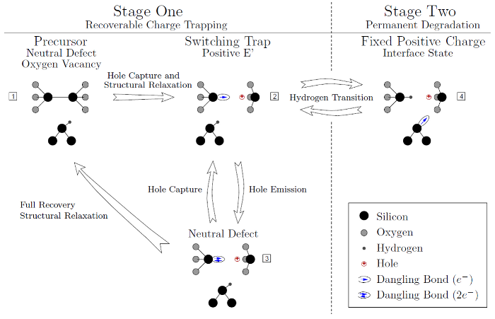
 bond breaks and a positively charged
 center is created (state 2). Upon hole emission (electron capture) the
 center is neutralized (state 3). Then being in this state, there are two
options. Either hole capture again moves the defect back to (state 2), making
it act as switching trap, or the defect structure totally relaxes back to its
equilibrium configuration (state 1). The transition between stage-one and
stage-two is assumed to be via hydrogen transition between state 2 and 4.
The dangling bond of the switching trap in (state 2) can capture a hydrogen
atom, leaving back a dangling bond at the interface. This passivation by the
hydrogen effectively locks the defect state in the positive charge (state 4).
center is neutralized (state 3). Then being in this state, there are two
options. Either hole capture again moves the defect back to (state 2), making
it act as switching trap, or the defect structure totally relaxes back to its
equilibrium configuration (state 1). The transition between stage-one and
stage-two is assumed to be via hydrogen transition between state 2 and 4.
The dangling bond of the switching trap in (state 2) can capture a hydrogen
atom, leaving back a dangling bond at the interface. This passivation by the
hydrogen effectively locks the defect state in the positive charge (state 4).
In this way positive  centers (state 2) are created which can now emit a
hole and transfer to (state 3). Being at (state 3) the neutralized defect has
either the choice to capture a hole and act as a switching trap by hopping
between state 2 and 3 [147], or to fully relax back to its initial precursor
state again (state
centers (state 2) are created which can now emit a
hole and transfer to (state 3). Being at (state 3) the neutralized defect has
either the choice to capture a hole and act as a switching trap by hopping
between state 2 and 3 [147], or to fully relax back to its initial precursor
state again (state  ). Each path finally leads to (state 1).
Therefore, this stage-one describes the recoverable part of the charge
trapping.
). Each path finally leads to (state 1).
Therefore, this stage-one describes the recoverable part of the charge
trapping.
When the two-stage model is fitted to experimental data of  ,
,  ,
and high-k devices, the strong (quadratic) voltage and (linear) temperature
dependence is predicted correctly supporting the theory of a broad distribution of
energetic defects. By involving both oxide charges and interface states
contributing to BTI, the model is furthermore able to describe the asymmetric
behavior during stress and recovery and the strong bias sensitivity during
recovery [98].
,
and high-k devices, the strong (quadratic) voltage and (linear) temperature
dependence is predicted correctly supporting the theory of a broad distribution of
energetic defects. By involving both oxide charges and interface states
contributing to BTI, the model is furthermore able to describe the asymmetric
behavior during stress and recovery and the strong bias sensitivity during
recovery [98].
The coupling is established via the transition of a hydrogen atom located at
the interface between state 2 and 4. This transition is determined by the hole
concentration (positive  centers) and by the number of hydrogen passivated
silicon dangling bonds both available at the interface, i.e. the occupancy of (state
2). When the defect is moved from (state
centers) and by the number of hydrogen passivated
silicon dangling bonds both available at the interface, i.e. the occupancy of (state
2). When the defect is moved from (state  ), the dangling bond of the
oxide defect becomes passivated, leaving back a
), the dangling bond of the
oxide defect becomes passivated, leaving back a  center [139]. Since a
  center is a rather stable configuration compared to the switching trap, i.e. the
transition rates (state
center is a rather stable configuration compared to the switching trap, i.e. the
transition rates (state  ) are larger than the switching trap rates
(state
) are larger than the switching trap rates
(state  ), the positive defect is hence locked. Consequently, an
increased number of defects being in (state 2) favours the creation of
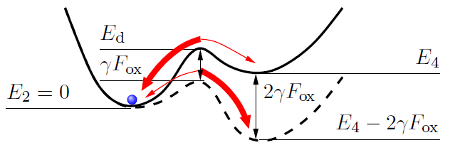
permanent states. Mathematically the transition between state 2 and 4
is modeled by thermal activation over a field-dependent barrier, which
besides the different ground states
), the positive defect is hence locked. Consequently, an
increased number of defects being in (state 2) favours the creation of
permanent states. Mathematically the transition between state 2 and 4
is modeled by thermal activation over a field-dependent barrier, which
besides the different ground states  and
and  , and its corresponding
dissociation barrier
, and its corresponding
dissociation barrier  heavily depends on the applied field
  , cf. Fig. 8.5
[98].
, cf. Fig. 8.5
[98].
 [98].
Without applied electric field this results in the solid defect configuration.
When applying an electric field
[98].
Without applied electric field this results in the solid defect configuration.
When applying an electric field  , the barriers are altered. Consequently
the transition rates are changed by the factor
, the barriers are altered. Consequently
the transition rates are changed by the factor  with respect
to the zero-field case. Here ‘
with respect
to the zero-field case. Here ‘ ’ holds for the transition (
 ) and ‘
 ’
for (
’
for ( ), with
  being the dipole moment [62]. The transition rates
are highlighted by differently thick arrows, indicating that the transition
(
being the dipole moment [62]. The transition rates
are highlighted by differently thick arrows, indicating that the transition
( ) is favored, while that of (
 ) is suppressed by the higher
  .
.