Due to the fact that the point defects disturb the regular order of the atoms in crystalline materials they influence the ion trajectories especially if an ion moves within a channel. The probability that a particle is removed from the channel (de-channeling) is increased by the presence of point defects. Therefore it is very important to consider the material damage during the calculation of a particle trajectory because the average range of a particle especially in the channeling region is significantly reduced by the accumulating damage.
Point defects are treated in the simulation by randomly neglecting lattice
atoms and by randomly inserting interstitial atoms as collision partners for a
moving particle (Sec. 4.4.1). The probability
![]() that the
collision partner is a point defect is determined by the vacancy and the
interstitial concentration. A linear model just considering the amorphization
concentration
that the
collision partner is a point defect is determined by the vacancy and the
interstitial concentration. A linear model just considering the amorphization
concentration
![]() as a saturation level has turned out to be
sufficient to adequately model the de-channeling effect.
as a saturation level has turned out to be
sufficient to adequately model the de-channeling effect.
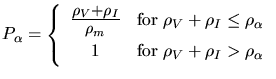 |
(3.174) |
When inserting interstitial atoms in the simulation care has to be taken to
conserve the local material density ![]() determined by the material
density
determined by the material
density ![]() , the vacancy concentration
, the vacancy concentration ![]() the interstitial
concentration
the interstitial
concentration ![]() .
.
 |
 |
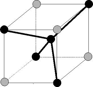
First they can be placed at tetrahedral interstitial sites. This is a reasonable
assumption because it is one of the two stable interstitial positions in a diamond
lattice ([66]). At these positions the interstitials form regular
tetrahedra with lattice atoms as indicated in Fig. 3.3.5. But as
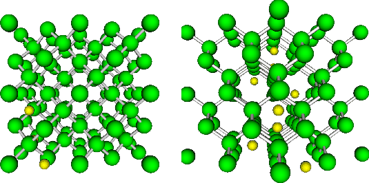
stated by Hobler et al. [37] de-channeling from the ![]() 100
100![]() channel is underestimated because the tetrahedral interstitial sites are in
the
channel is underestimated because the tetrahedral interstitial sites are in
the ![]() 100
100![]() atom rows while they are in the middle of the
atom rows while they are in the middle of the ![]() 110
110![]() channel as
shown in Fig. 3.16. The probability for a collision of
particle with an interstitial placed at a tetrahedral interstitial sites is
therefore significantly lower if the particle moves within an
channel as
shown in Fig. 3.16. The probability for a collision of
particle with an interstitial placed at a tetrahedral interstitial sites is
therefore significantly lower if the particle moves within an ![]() 100
100![]() channel
than if it moves within an
channel
than if it moves within an ![]() 110
110![]() channel.
channel.
To overcome this problem the actual position of an interstitial can be randomly smeared around the tetrahedral interstitial position as proposed by Posselt [64].
Alternatively an interstitial can be placed completely random within a certain area around the current position of the incident particle (Sec. 4.4.1). If this done only care has to be taken that the material density is preserved (3.175). Additionally it is not necessary to individually model the influence of vacancies and interstitials on a particle trajectory.
![]()
![]()
![]()
![]() Previous: 3.3.5.4 Amorphization
Up: 3.3.5 Material Damage -
Next: 4. Monte-Carlo Simulation with
Previous: 3.3.5.4 Amorphization
Up: 3.3.5 Material Damage -
Next: 4. Monte-Carlo Simulation with