An everlasting challenge for MEMS engineering is to fabricate a free-standing cantilever without any unwanted deflection, but in practice the thin films can not be deposited stress free. These effects of stress in free-standing MEMS structures can be demonstrated most plausibly with the cantilever deflection problem. Such a deflection of a 400 ![]() m long and 10
m long and 10 ![]() m thick fabricated cantilever is shown in Fig. 9.1.
m thick fabricated cantilever is shown in Fig. 9.1.
Fig. 9.2 shows the schematic structure of a free-standing cantilever, where the SiGe structural layer is deposited on the SiO![]() sacrificial layer. In this case it is assumed that there does not exist any stress gradient in the SiGe film, and so no deformation of the released cantilever occurs after removal of the underlying sacrificial material by etching.
sacrificial layer. In this case it is assumed that there does not exist any stress gradient in the SiGe film, and so no deformation of the released cantilever occurs after removal of the underlying sacrificial material by etching.
Normally the structural layer is not deposited stress free and therefore the bending of the released cantilever depends on the stress distribution over the layer thickness before release. In this context only the stress above and under the neutral bending line is responsible for the direction of the deflection, because stress causes forces which result in the bending moments regarding the neutral bending line. If the sum of the moments under the neutral bending line is larger than the above one, than the deflection is upward, otherwise downward. The neutral bending line is always located in the middle of the cantilever and, therefore, its location is changing with the layer thickness.
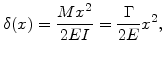
For an assumed linear stress gradient ![]() over thickness and a rectangular cross-section area
over thickness and a rectangular cross-section area ![]() of the beam with a width
of the beam with a width ![]() and thickness
and thickness ![]() , the deflection of the cantilever
, the deflection of the cantilever ![]() at position
at position ![]() is
is
Fig. 9.3 shows three possible forms of stress distribution and gradients in the fixed cantilever on the left and the corresponding direction of deflection on the right.
|
a) ![\includegraphics[width=0.67\linewidth]{fig/canti2}](img954.png)
b) ![\includegraphics[width=0.67\linewidth]{fig/canti4}](img955.png)
c) ![\includegraphics[width=0.67\linewidth]{fig/canti3}](img956.png) |
In the first situation with a positive stress gradient (Fig. 9.3a), the part of the beam above the neutral bending line is in a tensile state while the part below is in a dominant compressive state. Compressive stress in a body is an indication that the material has desire to expand, but the expansion is prevented. In the conventional declaration compressive stress always has a negative sign, so that the pressure can be positive as quoted in (7.15). Therefore, after release of the beam the upper tensile part can contract and the compressive one can dilate and, therefore, it is comprehensible that the deflection can only go upward.
The next case in Fig. 9.3b demonstrates that is is not necessary to have stresses with opposite sign on the two sides of the neutral bending line for a deflection. Here all stresses have compressive character, but due to the positive stress gradient the compressive stress values and the moments below the neutral bending line are larger than above. Therefore, there is also a deflection in the upward direction. In contrast to the previous configurations the stress gradient in the last case (see Fig. 9.3c) is negative. This situation is inverse to the first one, because there is an upper compressive part and a bottom tensile part. In consequence the cantilever deflection goes downward after release.
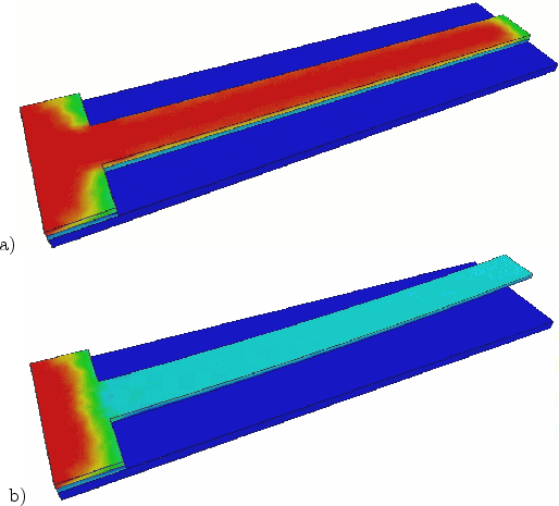
As example for a positive stress gradient in thin films (see Fig. 9.3a), where only tensile stress was assumed, the stress distributions for a 1 mm long and 10 ![]() m thick cantilever structure were simulated. As long as the cantilever is attached with the underlying SiO
m thick cantilever structure were simulated. As long as the cantilever is attached with the underlying SiO![]() -layer, the deposited SiGe film is under stress and the cantilever can not deform. Because of the positive stress gradient the highest tensile stress, marked with red color, is on the top of the fixed cantilever as demonstrated in Fig. 9.4a. After removal of the sacrificial SiO
-layer, the deposited SiGe film is under stress and the cantilever can not deform. Because of the positive stress gradient the highest tensile stress, marked with red color, is on the top of the fixed cantilever as demonstrated in Fig. 9.4a. After removal of the sacrificial SiO![]() -layer by etching, the SiGe beam is free standing. Now the cantilever can deform and the stress is relaxed, as shown in Fig. 9.4b. The intrinsic stress in the deposited SiGe layer is the driving force for the cantilever deflection. As listed in the next Section 9.2, there are a number of intrinsic stress sources.
-layer by etching, the SiGe beam is free standing. Now the cantilever can deform and the stress is relaxed, as shown in Fig. 9.4b. The intrinsic stress in the deposited SiGe layer is the driving force for the cantilever deflection. As listed in the next Section 9.2, there are a number of intrinsic stress sources.
 |
![\includegraphics[width=0.6\linewidth]{IMEC/S20B_03.ps}](img946.png)
![\includegraphics[width=0.65\linewidth]{fig/canti1}](img947.png)