In the third step of the design process the effect of edge
roughness is introduced. The inset of Fig. 3.22-c shows the
influence of edge roughness on the transmission of the ZGNR(20) of
length
![]() . As also described in previous
studies [88,19], in the first conduction plateau
the effect is negligible. In contrast to ZGNR, ELD-ZGNRs as well as
2ELD-ZGNRs are affected by edge roughness. This is because the
bandstructure of these GNRs has undergone a band folding, and
therefore, the states in the first conduction plateau have lower wave
vectors. As the long range defects can induce only a small momentum transfer, the momentum conservation rule indicates that, in
contrast to the ZGNR, the transport of ELD-ZGNRs and 2ELD-ZGNRs will
not remain ballistic in the presence of line edge roughness and long
range substrate impurities. This is shown in Fig. 3.22-c, where the transmission of a roughened
. As also described in previous
studies [88,19], in the first conduction plateau
the effect is negligible. In contrast to ZGNR, ELD-ZGNRs as well as
2ELD-ZGNRs are affected by edge roughness. This is because the
bandstructure of these GNRs has undergone a band folding, and
therefore, the states in the first conduction plateau have lower wave
vectors. As the long range defects can induce only a small momentum transfer, the momentum conservation rule indicates that, in
contrast to the ZGNR, the transport of ELD-ZGNRs and 2ELD-ZGNRs will
not remain ballistic in the presence of line edge roughness and long
range substrate impurities. This is shown in Fig. 3.22-c, where the transmission of a roughened
![]() long ELD-ZGNR(10,10) channel (solid-blue line) is reduced by
long ELD-ZGNR(10,10) channel (solid-blue line) is reduced by ![]() compared to the ballistic value (dashed-black line). Edge
roughness degrades the conductivity of holes and electrons by a similar amount, and therefore, the level of asymmetry around the Fermi level is retained.
compared to the ballistic value (dashed-black line). Edge
roughness degrades the conductivity of holes and electrons by a similar amount, and therefore, the level of asymmetry around the Fermi level is retained.
|
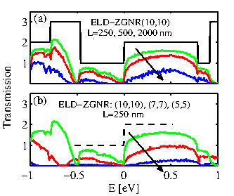
Figures 3.23-a and 3.23-b illustrate the
influence of roughness in ELD-ZGNR channels on their transmission, for channels of different lengths and widths. In this calculation positive impurities are also
included. Figure 3.23-a shows the transmission of edge
roughened ELD-ZGNR(10,10) versus energy for the channel lengths
![]() ,
, ![]() , and
, and
![]() . As the channel length is increased, the
transmission drops further compared to the transmission of the ideal
channel (black-solid line). This is expected since the channel
resistance increases with increasing length. Figure
3.23-b illustrates the effect of the ribbon's width on the
transmission of ELD-ZGNRs with rough edges. In this case the length is
kept constant at
. As the channel length is increased, the
transmission drops further compared to the transmission of the ideal
channel (black-solid line). This is expected since the channel
resistance increases with increasing length. Figure
3.23-b illustrates the effect of the ribbon's width on the
transmission of ELD-ZGNRs with rough edges. In this case the length is
kept constant at
![]() , and results for three different ribbons
with parameters (10,10), (7,7), and (5,5) are shown. As the width of
the ribbon is decreased, the effect of line edge roughness scattering
on the transmission becomes stronger because the carriers reside on
average closer to the edges.
, and results for three different ribbons
with parameters (10,10), (7,7), and (5,5) are shown. As the width of
the ribbon is decreased, the effect of line edge roughness scattering
on the transmission becomes stronger because the carriers reside on
average closer to the edges.
It is worth mentioning that the effect of edge roughness on the transmission is much stronger in AGNR than in ZGNR. Although in the case of some AGNRs a bandgap is naturally present and the asymmetry need not be created with the introduction of line defects and impurities, the conductance is severely degraded by the roughness which renders this type of ribbon not well suited for transport applications [88]. (Note that edge roughness will be needed in order to reduce thermal conductivity as will be shown below.)
|
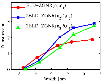
As we mentioned above in Fig. 3.21, the channel which
includes two ELDs can shift the majority of the
current spectrum in the region between the two ELDs, and thus farther
away from the edges. It is therefore expected that the 2ELD-ZGNR will
be less affected by edge roughness scattering than the ELD-ZGNR. A
comparison of the transmission of these devices with rough edges is
shown in Fig. 3.24. The transmission of
ELD-ZGNR(![]() ,
,![]() ), and two cases of 2ELD-ZGNR,
2ELD-ZGNR(
), and two cases of 2ELD-ZGNR,
2ELD-ZGNR(![]() ,4,
,4,![]() ) and the 2ELD-ZGNR(
) and the 2ELD-ZGNR(![]() ,6,
,6,![]() ) at
) at
![]() versus their width
versus their width ![]() are compared. The
parameters
are compared. The
parameters ![]() are adjusted such that the three channels have nearly
the same width
are adjusted such that the three channels have nearly
the same width ![]() . The first channel belongs to the category shown in
Fig. 3.21-a, the second in the category of
Fig. 3.21-b, and the third in the category of
Fig. 3.21-c. The third channel as shown in
Fig. 3.21 spreads the current spectrum more uniformly in
the channel and is expected to be affected the most from edge
roughness. All channels have the same length of
. The first channel belongs to the category shown in
Fig. 3.21-a, the second in the category of
Fig. 3.21-b, and the third in the category of
Fig. 3.21-c. The third channel as shown in
Fig. 3.21 spreads the current spectrum more uniformly in
the channel and is expected to be affected the most from edge
roughness. All channels have the same length of
![]() . For
smaller widths the effect of roughness is strong, and the
transmissions of all channels are drastically reduced. Since the
2ELD-ZGNR devices can concentrate the current spectrum around the
defect lines as shown in Fig. 3.21-b and
3.21-c, they effectively bring it closer to the edges and
the reduction is larger for these devices. For larger widths the
transmission of the ribbons approaches its ballistic value, which is 2
for the ELD-ZGNR devices and 3 for the 2ELD-ZGNR devices. The
transmission of the 2ELD-ZGNR(
. For
smaller widths the effect of roughness is strong, and the
transmissions of all channels are drastically reduced. Since the
2ELD-ZGNR devices can concentrate the current spectrum around the
defect lines as shown in Fig. 3.21-b and
3.21-c, they effectively bring it closer to the edges and
the reduction is larger for these devices. For larger widths the
transmission of the ribbons approaches its ballistic value, which is 2
for the ELD-ZGNR devices and 3 for the 2ELD-ZGNR devices. The
transmission of the 2ELD-ZGNR(![]() ,4,
,4,![]() ) channels increases
faster with increasing channel width, because the current spectrum is located farther from the
edges which makes it less susceptible to scattering as the width
increases. The transmission of 2ELD-ZGNR(
) channels increases
faster with increasing channel width, because the current spectrum is located farther from the
edges which makes it less susceptible to scattering as the width
increases. The transmission of 2ELD-ZGNR(![]() ,6,
,6,![]() ) channel
eventually increases close to the ballistic transmission value as the
width increases, but it increases more slowly than that of the
2ELD-ZGNR(
) channel
eventually increases close to the ballistic transmission value as the
width increases, but it increases more slowly than that of the
2ELD-ZGNR(![]() ,4,
,4,![]() ) channel.
) channel.