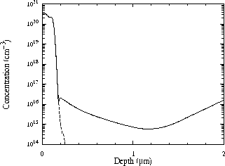
Figure 4.5: N-channel source/drain 1D doping profiles: SIMS donor profile (dashed line) and net doping extracted by inverse modeling from diode capacitance with area of
 .
.


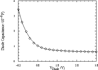
The extracted source/drain profile is shown in Fig. 4.5 together with the measured SIMS donor profile for an N-channel device. In Fig. 4.6 a comparison of the experimental C-V reverse junction characteristics with simulations using the extracted profile exemplifies the good fit achieved.

Figure 4.5: N-channel source/drain 1D doping profiles: SIMS donor profile (dashed
line) and net doping extracted by inverse modeling from diode capacitance
with area of  .
.

Figure 4.6: Simulated and experimental (symbols) reverse junction capacitance
of a  area diode.