
Previous: 3.3 Implementation of Grids Up: 3.3 Implementation of Grids Next: 3.3.2 Boundary Grids
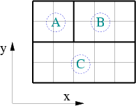
Segments represent local areas within a device. Each segment is assigned a grid which is the corresponding part of the device grid. Grid points at the interface to other segments are doubled. To handle this, segment grid points are implemented as references to the device grid points. Within the segment grid these references are treated as grid points of the segment. All other information stored for segment grids refer to these imaginary grid points.
The segment grid structure contains an array of indices of those grid point
coordinates in the device coordinate array which belong to the segment. A
simple example of a small device with three segments is shown in
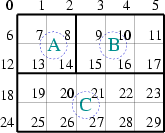
Fig. 3.1. The indices stored in the array for
segment A are 0, ![]() ,
, ![]() ,
, ![]() ,
, ![]() ,
, ![]() ,
, ![]() ,
, ![]() ,
, ![]() shown in
Fig. 3.1(c).
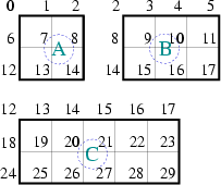
This approach allows to determine the
coordinates of each segment very quickly. The indices which are used by
subsequent segment grid information are shown in
Fig. 3.1(d).
shown in
Fig. 3.1(c).
This approach allows to determine the
coordinates of each segment very quickly. The indices which are used by
subsequent segment grid information are shown in
Fig. 3.1(d).
|
|
|
|
|
|
Another list stores the box volumes for every grid point of the segment in the same order. The box volumes refer to the points denoted by the elements of the array.
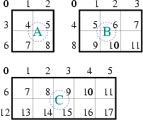
The point connectivity list which represents the grid lines is stored for each
segment. As an example Fig. 3.2 shows the
connectivity list for the grid of segment A. The connectivity list consists of
![]() lines. The lines start at the grid point
lines. The lines start at the grid point ![]() and end in
and end in
![]() . The lines must be unique and need not be sorted. The direction
can be chosen at random.
For each line the distance
. The lines must be unique and need not be sorted. The direction
can be chosen at random.
For each line the distance
![]() of the points
of the points ![]() and
and
![]() is stored. Furthermore, the fraction of the area
is stored. Furthermore, the fraction of the area
![]() between the two Voronoi boxes
between the two Voronoi boxes ![]() and
and ![]() and the distance of the
points
and the distance of the
points
![]() is stored which is required by the box
integration method.
is stored which is required by the box
integration method.
Robert Klima 2003-02-06