, voltage
  , charge
  , and flux
  , where
  and
and  are defined as the time integrals of
  and
and  , respectively [71].
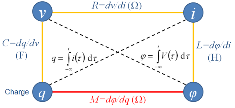
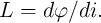
The four fundamental circuit variables are electric current , voltage , charge , and flux , where
and are defined as the time integrals of and , respectively [71].
 | (2.1) |
 | (2.2) |
The three conventional two-terminal basic circuit elements resistor, capacitor, and inductor are defined in terms of the constitutive relationships between two of these four variables as [68]
 | (2.3) |
 | (2.4) |
 | (2.5) |
 ,
,  , and
, and  are the resistance, capacitance, and inductance, respectively. Eq. 2.1-Eq. 2.5 express five
from six possible relations between the fundamental circuit variables (Fig. 2.1). For the sake of completeness,
Leon Chua postulated the existence of a fourth fundamental two-terminal circuit element called memristor
(memory resistor) [68] characterized by a constitutive relationship between
are the resistance, capacitance, and inductance, respectively. Eq. 2.1-Eq. 2.5 express five
from six possible relations between the fundamental circuit variables (Fig. 2.1). For the sake of completeness,
Leon Chua postulated the existence of a fourth fundamental two-terminal circuit element called memristor
(memory resistor) [68] characterized by a constitutive relationship between  and
and  in which
 and
and  are not necessarily accessible to any physical interpretation [71]. The constitutive
relation of charge-controlled and flux-controlled memristors are obtained as Eq. 2.6 and Eq. 2.7,
respectively [71].
are not necessarily accessible to any physical interpretation [71]. The constitutive
relation of charge-controlled and flux-controlled memristors are obtained as Eq. 2.6 and Eq. 2.7,
respectively [71].
 | (2.6) |
 | (2.7) |
By taking the time derivatives we obtain
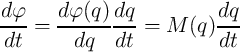 | (2.8) |
and
 | (2.9) |
where
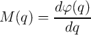 | (2.10) |
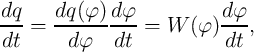
and
 | (2.11) |
are the memristance and the memductance of the memristors as a function of  and
and  , respectively.
 and
and  have the units of Ohms (
 ) and Siemens (S) as according to the definitions (Eq. 2.1
and Eq. 2.2) we have
) and Siemens (S) as according to the definitions (Eq. 2.1
and Eq. 2.2) we have  and
and  and thus we can simplify Eq. 2.8 and Eq. 2.9 to Eq. 2.12
and Eq. 2.13, respectively.
and thus we can simplify Eq. 2.8 and Eq. 2.9 to Eq. 2.12
and Eq. 2.13, respectively.
 | (2.12) |
 | (2.13) |
In fact, a charge (flux)-controlled memristor is characterized by a  curve and its memristance
(memductance) at
curve and its memristance
(memductance) at  (
( ) is equal to the slope of the curve
  (
( ). A device with
 (
( ) is just a linear resistor (conductor), while if
  (
( ) the device operates like a variable resistor (conductor) and exhibits memristive behavior.
In Chapter 6 we will see that memristors with
) the device operates like a variable resistor (conductor) and exhibits memristive behavior.
In Chapter 6 we will see that memristors with  (
( ) are suited for a
new charge (flux)-based memristive sensing scheme.
) are suited for a
new charge (flux)-based memristive sensing scheme.
The memristor acts as a programmable resistor since its electrical resistance depends on the time integral of
the applied current/voltage. Ideally, when the power is turned off ( ), the memristor preserves its
resistance forever, as the values of
), the memristor preserves its
resistance forever, as the values of  and
and  are left unchanged [71]. Therefore, it records the
historic profile of the applied current or voltage in the memristance/memductance which can
be revealed instantaneously by measuring its electrical resistance. This is a unique property of
memristors which cannot be realized by electric circuits combining resistors, capacitors, and inductors.
The most straightforward application of a memristor is non-volatile memory either as an analog
(continuously tunable or multilevel) memory or as a digital switch, depending on the physical operating
mechanisms of the resistance switching in the memristive device. In general, one can say a memristor
operates as an analog device in a low-voltage regime, while under large voltages it operates as a
digital switch between two states, characterized by low and high resistances corresponding to the
minimum and the maximum achievable resistance values limited by the physical properties of the
device.
are left unchanged [71]. Therefore, it records the
historic profile of the applied current or voltage in the memristance/memductance which can
be revealed instantaneously by measuring its electrical resistance. This is a unique property of
memristors which cannot be realized by electric circuits combining resistors, capacitors, and inductors.
The most straightforward application of a memristor is non-volatile memory either as an analog
(continuously tunable or multilevel) memory or as a digital switch, depending on the physical operating
mechanisms of the resistance switching in the memristive device. In general, one can say a memristor
operates as an analog device in a low-voltage regime, while under large voltages it operates as a
digital switch between two states, characterized by low and high resistances corresponding to the
minimum and the maximum achievable resistance values limited by the physical properties of the
device.
Since the memristor is a passive device, its current-voltage characteristic exhibits a hysteresis loop pinched at
the origin and confined to the first and the third quadrants [71]. In fact, when the current (voltage) applied
to the memristor goes to zero at  , the memristor acts as an ordinary resistor (conductor)
with a finite resistance
, the memristor acts as an ordinary resistor (conductor)
with a finite resistance  (conductance
  ) and thus the voltage (current) of the
memristor goes to zero as well. Therefore, the
) and thus the voltage (current) of the
memristor goes to zero as well. Therefore, the  curve passes through the origin and pinches the
memristor hysteresis loop. It is clear that the
curve passes through the origin and pinches the
memristor hysteresis loop. It is clear that the  characteristics of any nonlinear resistor (e.g.
memristor) cannot be a straight line that passes through the origin, otherwise it is a linear resistor.
Four decades after Chua’s seminal paper ([68]) on memristor, he recently has shown that all
forms of two-terminal non-volatile memories based on resistance switching can be classified as
memristor since they demonstrate memristor fingerprint characterized as a pinched
characteristics of any nonlinear resistor (e.g.
memristor) cannot be a straight line that passes through the origin, otherwise it is a linear resistor.
Four decades after Chua’s seminal paper ([68]) on memristor, he recently has shown that all
forms of two-terminal non-volatile memories based on resistance switching can be classified as
memristor since they demonstrate memristor fingerprint characterized as a pinched  hysteresis
loop [71, 72].
hysteresis
loop [71, 72].
The definition of a memristor can be extended to a (passive two-terminal) memristive system [70] described by two coupled equations as
 | (2.14) |
called State-dependent Ohm’s law [71] and
 | (2.15) |
called State equation [71], where  is the voltage across the device,
  represents the generalized
(nonlinear) resistance of the device,
represents the generalized
(nonlinear) resistance of the device,  denotes a state variable which can be a vector
  ,
,
 is the current through the device, and
  expresses the functional dependence of
  on
on  and
and  .
The
.
The  curve passes through the origin
  as
as  [71]. As we will see later, the
state variable
[71]. As we will see later, the
state variable  can describe physically reasonable device parameters and thus this general definition of a
memristive system can be successfully utilized to model various memristive devices with different operating
mechanisms.
can describe physically reasonable device parameters and thus this general definition of a
memristive system can be successfully utilized to model various memristive devices with different operating
mechanisms.