A systematic study in a two conductor side-by-side structure over a ground
plane was done to investigate quantitatively the error introduced by choosing
a too small domain. We defined the test distance
![]() as the width of conductors, the distance between them, their thickness
and distance above the ground plane. From the analysis of several data tests
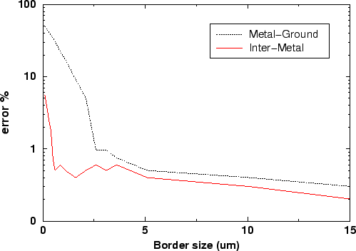
(see Figure 6.16 for the case where
as the width of conductors, the distance between them, their thickness
and distance above the ground plane. From the analysis of several data tests
(see Figure 6.16 for the case where
![]() )
we
obtained the rule of thumb stating that the domain of simulation
should be extended, at
least, by the maximum height of the structure. As it is
shown by Figure 6.16, this rule is related to the
capacitance to the ground: the inter-metal capacitance after
extending the domain by a few tens of micrometer becomes almost constant.
)
we
obtained the rule of thumb stating that the domain of simulation
should be extended, at
least, by the maximum height of the structure. As it is
shown by Figure 6.16, this rule is related to the
capacitance to the ground: the inter-metal capacitance after
extending the domain by a few tens of micrometer becomes almost constant.
The fluctuations of the error value at levels lower than 1% in Figure 6.16 are due to the simulation grid, which could not be kept constant. The influence of the grid on the error is very difficult to quantify, as it varies from structure to structure. However, the grid refinement criterium (the minAngle option of triangle [70]) must be tuned carefully to obtain reliable simulation results. One simple method is to use a small typical structure, start the simulation with a coarse grid and refine the grid until the result becomes independent of the grid refinement. Then use that value for the complete simulation. Naturally, this is only relevant for complex cases where memory consumption and simulation times can be a problem.
 |